Automatic grouting molding equipment for ceramic wine bottle
What is Al technical title?
Al technical title is built by PatSnap Al team. It summarizes the technical point description of the patent document.
A technology for automatic grouting and ceramic wine bottle application in ceramic molding machines, auxiliary molding equipment, supply devices, etc., which can solve the problem of affecting product yield and cost-effectiveness, easy formation of bubbles in slurry and mold, affecting product quality, etc. problem, to achieve the effect of low cost, high grouting efficiency and high grouting quality
Inactive Publication Date: 2021-02-12
黄佳怡
View PDF6 Cites 4 Cited by
Summary
Abstract
Description
Claims
Application Information
AI Technical Summary
This helps you quickly interpret patents by identifying the three key elements:
Problems solved by technology
Method used
Benefits of technology
Problems solved by technology
In the production process, due to the long process, each process requires a lot of manpower and material resources. A small problem in each process will eventually become a big problem, which directly affects the product yield and cost-effectiveness. In the existing In the production, the slurry is injected into the plaster mold, and after the belt absorbs water to form it, the excess slurry is poured out, and the solidified slurry forms the blank. However, in the production of the existing ceramic wine bottles, most of them are done manually. Grouting, the efficiency of grouting is low, and it is easy to form air bubbles between the slurry and the mold, which affects the product quality, and the cost is high. Therefore, we propose an automatic grouting molding equipment for ceramic wine bottles
Method used
Image
Click on the blue label to locate the original text in one second.
Reading with bidirectional positioning of images and text.
Examples
Embodiment Construction
[0021] The following will clearly and completely describe the technical solutions in the embodiments of the present invention with reference to the accompanying drawings in the embodiments of the present invention. Obviously, the described embodiments are only some, not all, embodiments of the present invention. Based on the embodiments of the present invention, all other embodiments obtained by persons of ordinary skill in the art without making creative efforts belong to the protection scope of the present invention.
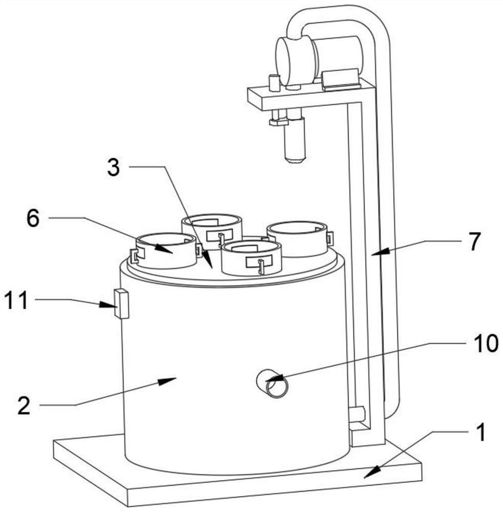
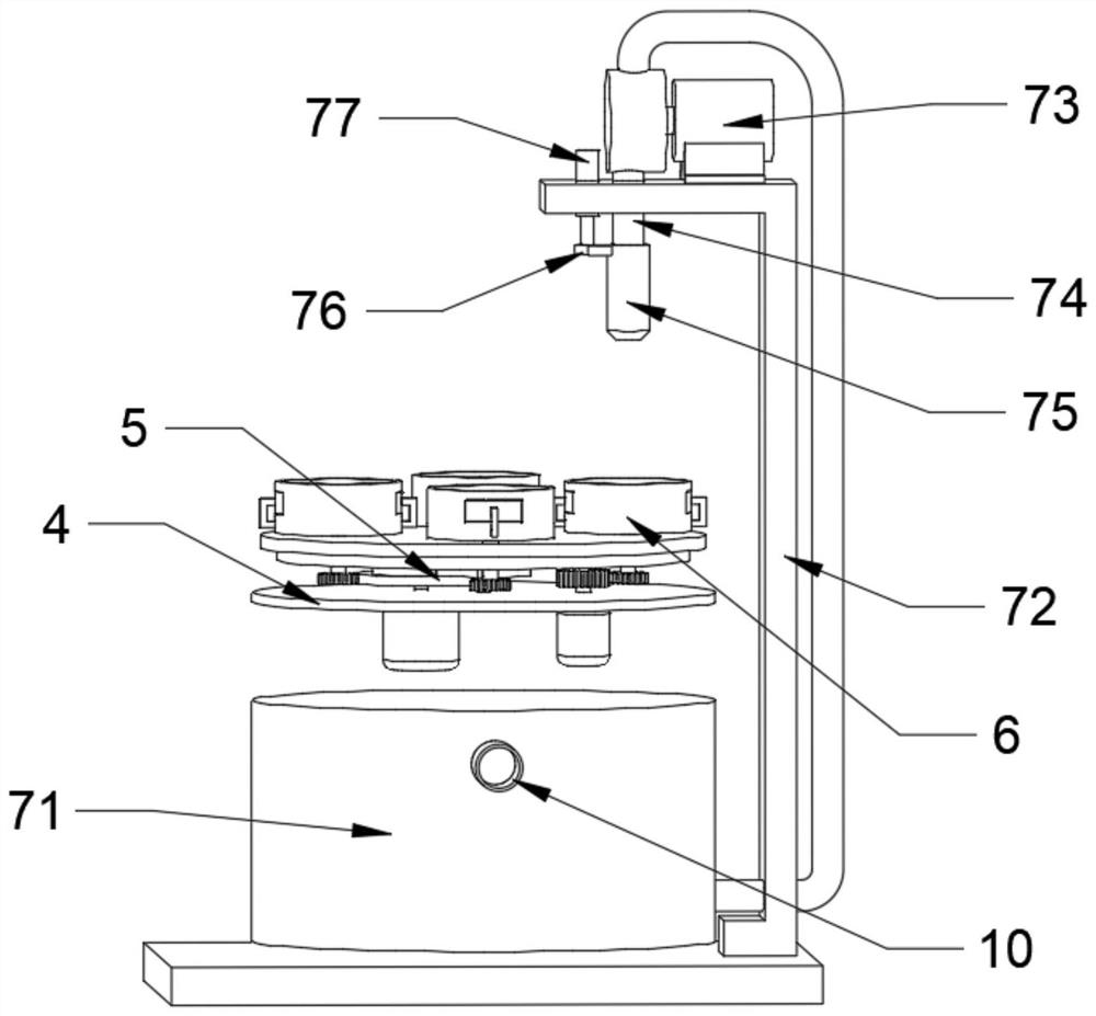
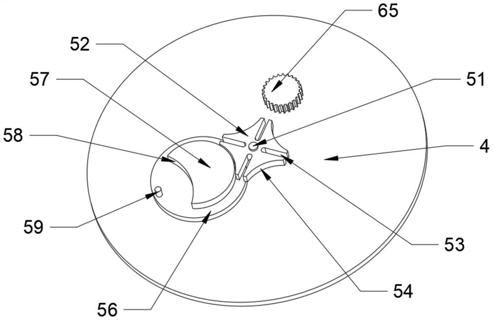
[0022] see figure 1 and figure 2 , an automatic grouting molding equipment for ceramic wine bottles in the illustration, including a bottom plate 1 and an equipment box 2, the upper surface of the bottom plate 1 is fixed with an equipment box 2, and the top of the equipment box 2 is connected to a workbench 3 through bearing rotation , the upper end of the inner wall of the equipment box 2 is fixed with a partition 4, the middle part of the partition 4 is fi...
PUM
Abstract
The invention discloses automatic grouting molding equipment for a ceramic wine bottle. The automatic grouting molding equipment comprises a bottom plate and an equipment box, and the equipment box isfixed to the upper surface of the bottom plate; the top of the equipment box is rotatably connected with a workbench through a bearing, and a partition plate is fixed to the upper end of the inner wall of the equipment box; a rotating mechanism which can be rotated at a fixed angle is fixed to the middle of the partition plate; rotatable fixing mechanisms are symmetrically installed on the surface of the workbench, and a grouting mechanism for preventing splashing is fixed to one end of the bottom plate; the rotating mechanism comprises a fixing shaft, a rotating plate, stirring grooved, locating grooved, a first servo motor, a rotating disc, a locating disc, an avoidance groove and a stirring column, and the fixing shaft is fixed to the middle of the workbench; and the bottom of the fixing shaft is rotatably connected with the middle of the partition plate through a bearing, and the rotating plate is fixed to the middle of the fixing shaft; and the stirring grooves and the locating grooves are formed in the surface of the rotating plate at equal intervals. According to the automatic grouting molding equipment, the mold grouting efficiency is higher, the cost is lower, the grouting quality is higher, and people can use the the automatic grouting molding equipment conveniently.
Description
technical field [0001] The invention relates to the technical field of ceramic wine bottle production, in particular to automatic grouting molding equipment for ceramic wine bottles. Background technique [0002] There are many processes for ceramic wine bottles, generally including material selection, awakening, ball milling, modeling, mold making, mold turning, grouting, demoulding, blank trimming, drying, glazing, bisque firing, glaze firing, decal baking, product selection, etc. process. In the production process, due to the long process, each process requires a lot of manpower and material resources. A small problem in each process will eventually become a big problem, which directly affects the product yield and cost-effectiveness. In the existing In the production, the slurry is injected into the plaster mold, and after the belt absorbs water to form it, the excess slurry is poured out, and the solidified slurry forms the blank. However, in the production of the exis...
Claims
Application Information
Patent Timeline
Application Date:The date an application was filed.
Publication Date:The date a patent or application was officially published.
First Publication Date:The earliest publication date of a patent with the same application number.
Issue Date:Publication date of the patent grant document.
PCT Entry Date:The Entry date of PCT National Phase.
Estimated Expiry Date:The statutory expiry date of a patent right according to the Patent Law, and it is the longest term of protection that the patent right can achieve without the termination of the patent right due to other reasons(Term extension factor has been taken into account ).
Invalid Date:Actual expiry date is based on effective date or publication date of legal transaction data of invalid patent.