A feedback control method and system based on pwm regenerative converter

An energy-feeding converter and control system technology, applied in the direction of power management, power lines, vehicle components, etc., can solve the problems of uncontrollable output voltage, misjudgment of PWM converter, and difficulty in accurately judging the running state of trains, etc., to achieve Solve the effect of stability and reliability, simple criterion

Active Publication Date: 2022-06-07
XIAN XJ POWER ELECTRONICS TECH
View PDF0 Cites 0 Cited by
  • Summary
  • Abstract
  • Description
  • Claims
  • Application Information

AI Technical Summary

Problems solved by technology

Diode rectifiers have the advantages of high efficiency, large capacity, and strong overload capacity. At the same time, they also have disadvantages such as uncontrollable output voltage, large ripple, and one-way energy flow that cannot be used for regenerative braking energy absorption and utilization.
However, the PWM converter is easy to cause misjudgment, and forms a power circulation with the diode rectifier unit, making it difficult to accurately judge the running state of the train, which is not conducive to the energy utilization of the track power supply system

Method used


Image

  • A feedback control method and system based on pwm regenerative converter
  • A feedback control method and system based on pwm regenerative converter

Examples


Embodiment Construction

[0037] In order to make the purposes, technical solutions and advantages of the embodiments of the present invention clearer, the technical solutions in the embodiments of the present invention will be clearly and completely described below with reference to the accompanying drawings in the embodiments of the present invention. Obviously, the described embodiments These are some embodiments of the present invention, but not all embodiments. The components of the embodiments of the invention generally described and illustrated in the drawings herein can be arranged and designed in a variety of different configurations.

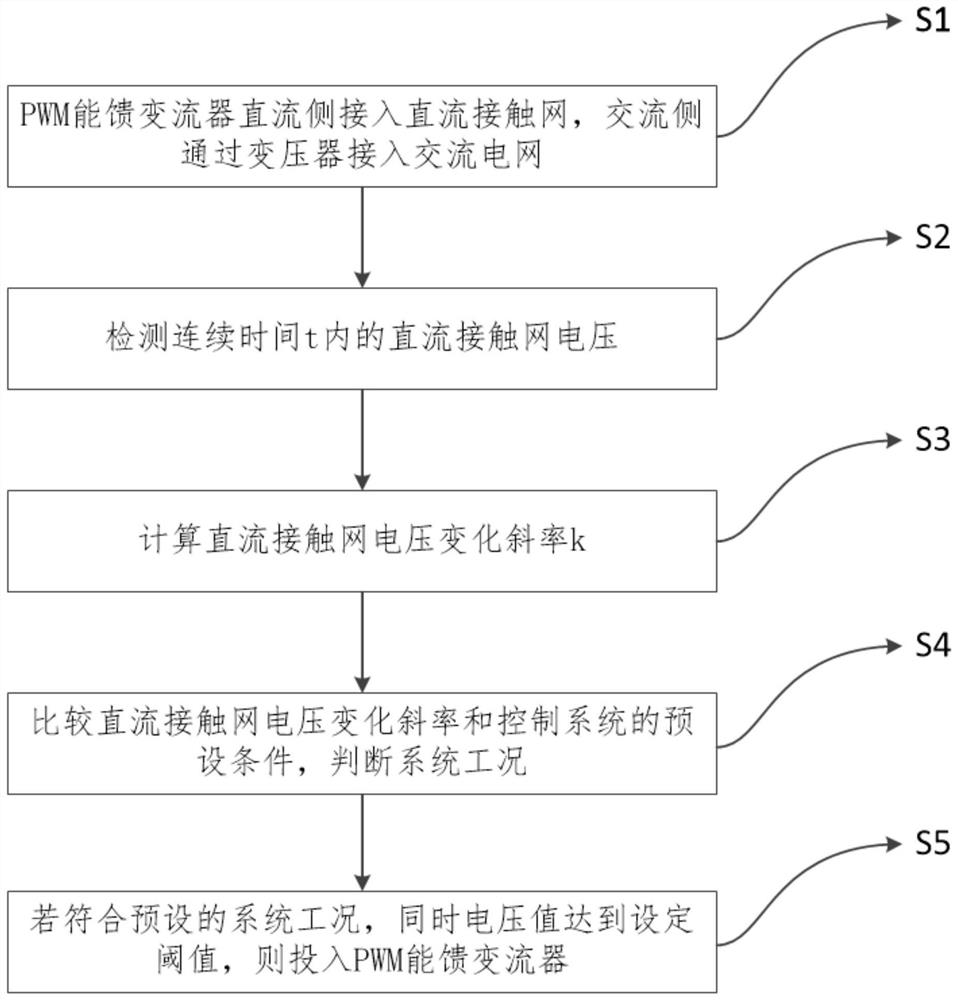
[0038] Please refer to Figure 1 to Figure 2 , the first embodiment of the present invention provides a feedback control method based on a PWM energy-feedback converter, including:

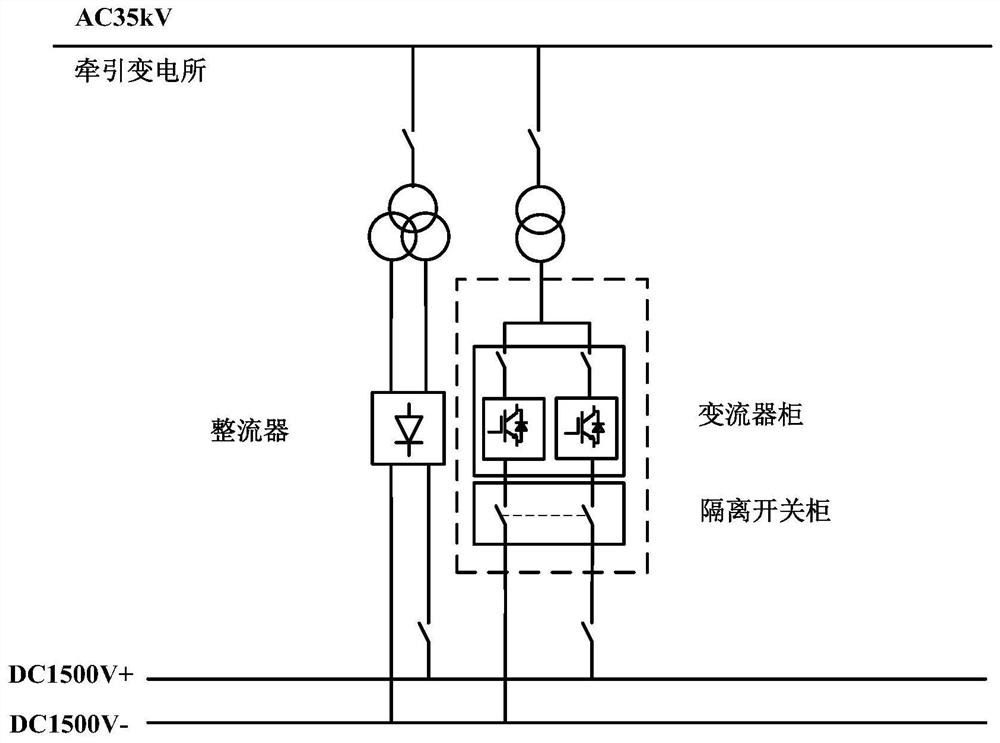
[0039] The DC side of the PWM energy-feeding converter is connected to the DC catenary, and the AC side is connected to the AC grid through the transformer.

[0040] Through the ...


PUM


Abstract

The invention discloses a feedback control method and system based on a PWM energy-feedback converter. The method includes: the DC side of the PWM energy-fed converter is connected to the DC catenary, and the AC side is connected to the AC grid through a transformer; detecting the DC catenary voltage within a continuous time t; calculating the DC catenary voltage change slope k; comparing the DC catenary The voltage change slope and the preset conditions of the control system determine the system working condition; if the preset system working condition is met, and the voltage value reaches the set threshold, the PWM energy-feeding converter is put into operation. The system includes: an energy-feedback converter access device, a voltage detection device, a slope calculation device, a working condition judgment device, and a feedback adjustment device. The invention can accurately judge the running state of the train through the change of the DC catenary voltage, solves the problem of stability and reliability in the engineering application of the PWM converter, thereby controlling the accurate input of the PWM rectifier, and achieving the purpose of energy saving in the power supply system , the criterion is simple and accurate.

Description

technical field [0001] The invention relates to the technical field of urban rail transit power supply, in particular to a feedback control method and system based on a PWM energy-feedback converter. Background technique [0002] In the existing urban rail transit power supply system, diode rectifiers are generally used as the power supply for trains. Diode rectifiers have the advantages of high efficiency, large capacity, strong overload capacity, etc., but also have disadvantages such as uncontrollable output voltage, large ripple, and unidirectional energy flow that cannot be used for regenerative braking energy absorption and utilization. When the train starts to run, the diode rectifier rectifies the work to provide traction energy to the train. When the train brakes, it is in the braking power generation mode, the DC bus voltage rises, the catenary voltage fluctuates within a certain range with the change of the train load on the catenary, and the PWM changes. The cur...

Claims


Application Information

Patent Timeline
Patent Type & Authority Patents(China)
IPC IPC(8): B60M3/00B60M3/06
CPCB60M3/00B60M3/06Y02T10/72
Inventor 孟向军黄辉李朋翔郎学斌郑月宾梅桂芳郜亚秋
Owner XIAN XJ POWER ELECTRONICS TECH
Why Eureka
Try Eureka