Two-specification core-spun ratio production equipment for optical fiber preform mandrel and method of two-specification core-spun ratio production equipment

A technology for optical fiber preforms and production equipment, applied in glass manufacturing equipment, manufacturing tools, etc., can solve problems such as easy scrapping, failure to meet shipment requirements, and time-consuming adjustments

Pending Publication Date: 2021-02-12
JIANGSU AOWEIXIN HENGTONG OPTICAL TECH
View PDF0 Cites 0 Cited by
  • Summary
  • Abstract
  • Description
  • Claims
  • Application Information

AI Technical Summary

Problems solved by technology

[0003] The core wrapping ratio of the mandrel is adjusted by adjusting the position of the core layer blowtorch, so each adjustment needs to wait until a loose body is deposited. The core wrapping ratio of a loose body is the same from the beginning to the end, because Due to the limitation of production capacity, the distribution of mandrels with core ratios of various specifications cannot meet the shipment requirements, and the specifications of core ratios need to be frequently switched for production. During the switching process, it takes time to adjust the machine and is prone to scrapping. Based on the above defects and deficiencies , it is necessary to improve the existing technology, and design a kind of production equipment and method for optical fiber prefabricated core rod with two specifications of core ratio

Method used


Image

  • Two-specification core-spun ratio production equipment for optical fiber preform mandrel and method of two-specification core-spun ratio production equipment
  • Two-specification core-spun ratio production equipment for optical fiber preform mandrel and method of two-specification core-spun ratio production equipment
  • Two-specification core-spun ratio production equipment for optical fiber preform mandrel and method of two-specification core-spun ratio production equipment

Examples


Embodiment Construction

[0022] The preferred embodiments of the present invention will be described in detail below in conjunction with the accompanying drawings, so that the advantages and features of the invention can be more easily understood by those skilled in the art, so as to define the protection scope of the present invention more clearly.

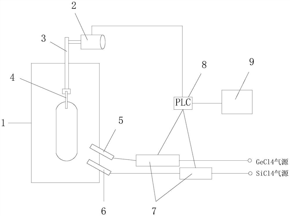
[0023] see Figure 1 to Figure 4 , the embodiment of the present invention includes:

[0024] An optical fiber prefabricated core rod uses two specifications of the core ratio production equipment. The optical fiber prefabricated rod core rod uses two specifications of the core ratio production equipment, including a deposition chamber 1, a lifting motor 2, a lifting rod 3, a target rod 4, Cladding blowtorch 5, core layer blowtorch 6, gas mass flow controller MFC7, PLC system 8 and man-machine interface 9, a lifting motor 2 is arranged on the outside of the deposition chamber 1, and the lifting motor 2 drives the lifting rod 3 to move upward, and the lif...


PUM


Abstract

The invention discloses two-specification core-spun ratio production equipment and method for an optical fiber preform core rod, and the equipment comprises a deposition cavity, a lifting motor, a lifting rod, a target rod, a cladding blowtorch, a core blowtorch, a gas mass flow controller MFC, a PLC system, and a man-machine interface. The lower end of the lifting rod is located in the depositioncavity, a target rod is installed at the lower end of the lifting rod and driven by a motor to rotate, a cladding blowtorch and a core blowtorch are installed in the deposition cavity, and the cladding blowtorch and the core blowtorch are connected with a GeCl4 gas source and a SiCl4 gas source through gas pipelines respectively. Gas mass flow controllers MFC are installed on the gas pipelines atthe cladding blowtorch and the core blowtorch respectively, the two gas mass flow controllers MFC and the lifting motor are connected to a PLC system through signal lines, and the PLC system is connected with a human-computer interface through a signal line. By means of the mode, the lifting speed is changed in the deposition process, one device can produce core-spun ratios of two specifications,and device switching is not needed.

Description

technical field [0001] The invention relates to the technical field of production of optical fiber prefabricated rods, in particular to a production equipment and a method for producing optical fiber prefabricated rods with two specifications of core cladding ratios. Background technique [0002] The optical fiber prefabricated core rod has two layers, which are called the core layer and the cladding layer. The optical signal is transmitted in the core layer. An important optical parameter of the core rod is the ratio of the diameter of the cladding layer to the core layer of the core rod, which is called Core ratio, in the VAD production process, two blowtorches are used to deposit the core layer and the cladding layer respectively. By adjusting the position of the core layer blowtorch, the diameter of the mandrel core layer can be adjusted, thereby achieving the purpose of adjusting the core ratio. VAD deposition is completed The product is called a loose body. The loose b...

Claims


Application Information

Patent Timeline
Patent Type & Authority Applications(China)
IPC IPC(8): C03B37/018C03B37/07
CPCC03B37/01861C03B37/01853C03B37/07
Inventor 李锐王侃骆金卫
Owner JIANGSU AOWEIXIN HENGTONG OPTICAL TECH
Why Eureka
Try Eureka