
High-pressure jet grouting pile waterproof curtain construction method

A technology of high-pressure jet grouting piles and water-stop curtains, which is applied in excavation, sheet pile walls, foundation structure engineering, etc., and can solve the problems of poor impermeability of water-stop curtains, holes or gaps of jet grouting piles, and relatively low spraying accuracy requirements. Advanced problems, achieve simple connection strength, avoid drilling collapse, and ensure the effect of generating quality

Active Publication Date: 2022-02-15
湖北武桥岩土工程有限公司
View PDF8 Cites 0 Cited by
  • Summary
  • Abstract
  • Description
  • Claims
  • Application Information

AI Technical Summary

Problems solved by technology

[0004] In view of the related technologies mentioned above, the inventor believes that there are the following defects: during the construction of the rotary grouting piles with interlocking structures, the requirements for the hardness of the soil are relatively high, and the soil quality When it is soft, the borehole of the plum-blossom structure is prone to collapse. Moreover, when high-pressure rotary spraying is carried out inside the borehole of the plum-blossom structure, the accuracy of the spraying grout is high. If the construction is inadvertent, it is easy to cause holes in the rotary grouting pile. or gaps, the impermeability of the water-stop curtain composed of rotary grouting piles will become worse

Method used


Image

  • High-pressure jet grouting pile waterproof curtain construction method
  • High-pressure jet grouting pile waterproof curtain construction method
  • High-pressure jet grouting pile waterproof curtain construction method

Examples


Embodiment Construction

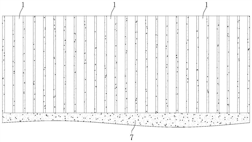
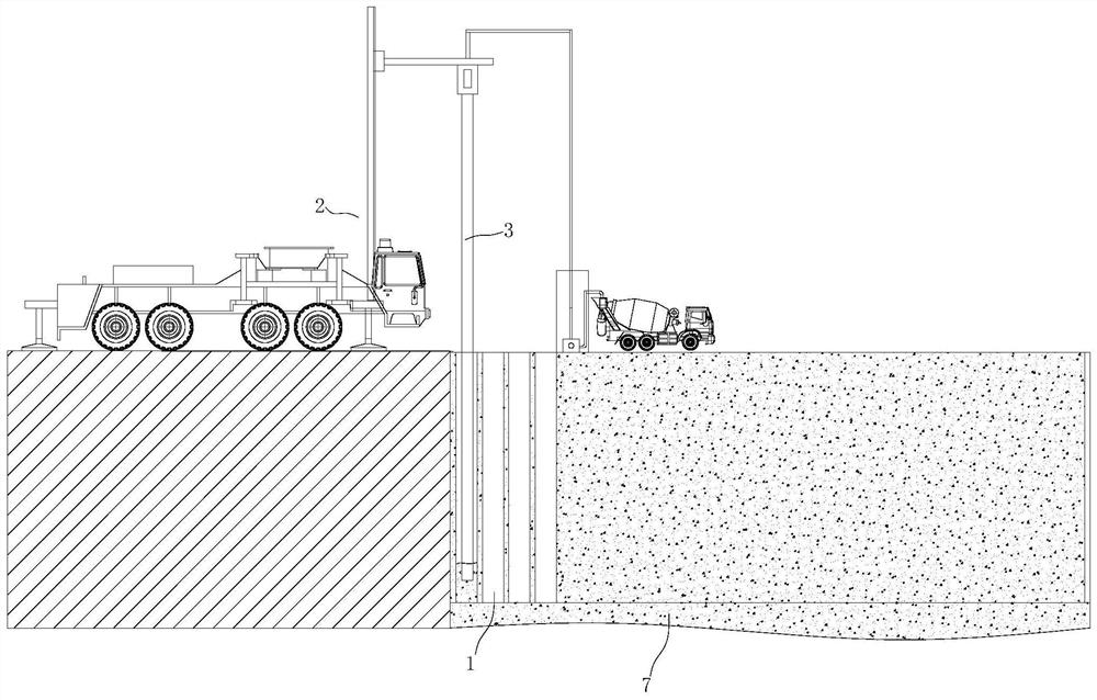
[0054] The following is attached Figure 1-11 The application is described in further detail.

[0055] The embodiment of the present application discloses a construction method for a water-stop curtain of a high-pressure rotary grouting pile. The construction method includes the following steps:

[0056] Step S1, planning of the construction area and ground cleaning: determine the area of ​​the construction area and the rules and shapes of the construction area according to the drawings, draw a line on the edge of the construction area through the paint, and the marking line of the paint is the construction line of the high-pressure rotary grouting pile. The area surrounded by the middle of the rotary grouting pile construction line is the construction area, and the debris on the land in the construction area should be cleaned to ensure that the construction area is empty and clean.

[0057] Step S2. Drill pilot holes on the construction route of high-pressure jet grouting pi...


PUM


Abstract

The invention relates to the field of building construction and particularly discloses a high-pressure jet grouting pile waterproof curtain construction method. The method comprises the following steps that S1, a construction area is planned, and the ground is cleaned; S2, pilot holes are drilled in a high-pressure jet grouting pile construction line on an edge of the planned area, and soil sampling is conducted through the pilot holes; S3, hole positions needing to be drilled in the high-pressure jet grouting pile construction line are determined according to the soil texture of the soil; S4, mechanical drilling is conducted on the marked hole positions; S5, a rotary spraying pipe is installed on a drilling machine; S6, a jet grouting pile is formed after the cement paste in the drilled hole is solidified; and S7, a building formwork is fixedly installed on an inner wall of the building foundation pit, side faces of the gaps between the adjacent jet grouting piles are sealed through the building formwork, cement paste is poured into the gaps between the adjacent jet grouting piles from the top of the building foundation pit, and a sealing curtain plate is formed after the cement paste is solidified. The method is advantaged in that the technology for forming the sealing curtain plate through pouring is simple, connecting strength of the interval type jet grouting piles can be guaranteed, and meanwhile impermeability of a waterproof curtain of the jet grouting piles is greatly improved.

Description

technical field [0001] The present application relates to the field of building construction, in particular to a construction method for a water-stop curtain of a high-pressure rotary grouting pile. Background technique [0002] High-pressure rotary grouting piles use high-pressure rotating nozzles to spray cement slurry into the soil layer and mix with the soil to form a continuous lapped cement reinforcement. A plurality of high-pressure rotary grouting piles are connected to each other to form a high-pressure rotary grouting pile water-stop curtain. The high-pressure rotary grouting pile water-stop curtain acts as a water stop on the inner wall of the building foundation pit to ensure the support strength and waterproof strength of the inner wall of the building foundation pit. . [0003] In order to improve the water-stop performance of the high-pressure jet grouting pile water-stopping curtain, some high-pressure jet-grinding piles adopt an interlocking structure durin...

Claims


Application Information

Patent Timeline
Patent Type & Authority Applications(China)
IPC IPC(8): E02D19/18E02D5/46E02D17/02E02D1/00
CPCE02D19/18E02D5/46E02D17/02E02D1/00
Inventor 姚爱民祝凯敏伍小农
Owner 湖北武桥岩土工程有限公司
Learn More