Triangle lock device

A triangular lock and lock body technology, which is applied in the field of triangular lock devices, can solve problems that affect the efficiency of inspection and maintenance, triangular locks cannot provide keys, and share keys, etc.

Pending Publication Date: 2021-02-12
GUANGZHOU GUANGRI ELEVATOR IND
View PDF0 Cites 1 Cited by
  • Summary
  • Abstract
  • Description
  • Claims
  • Application Information

AI Technical Summary

Problems solved by technology

The key needs to be inserted into the lock hole and rotated to the position where the trigger switch is turned on, and the key should not be detached during inspection and maintenance operations, so as to prevent the trigger switch from being unable to reset due to the detachment of the key, thereby threatening the operation safety of the elevator
[0003] Th

Method used


Image

  • Triangle lock device
  • Triangle lock device
  • Triangle lock device

Examples


Embodiment 1

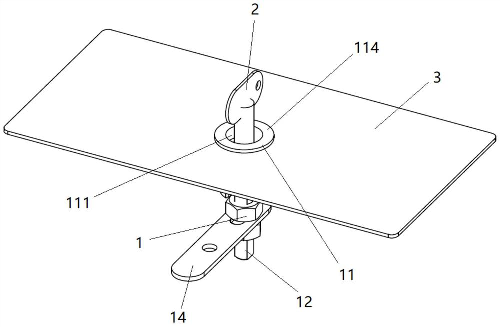
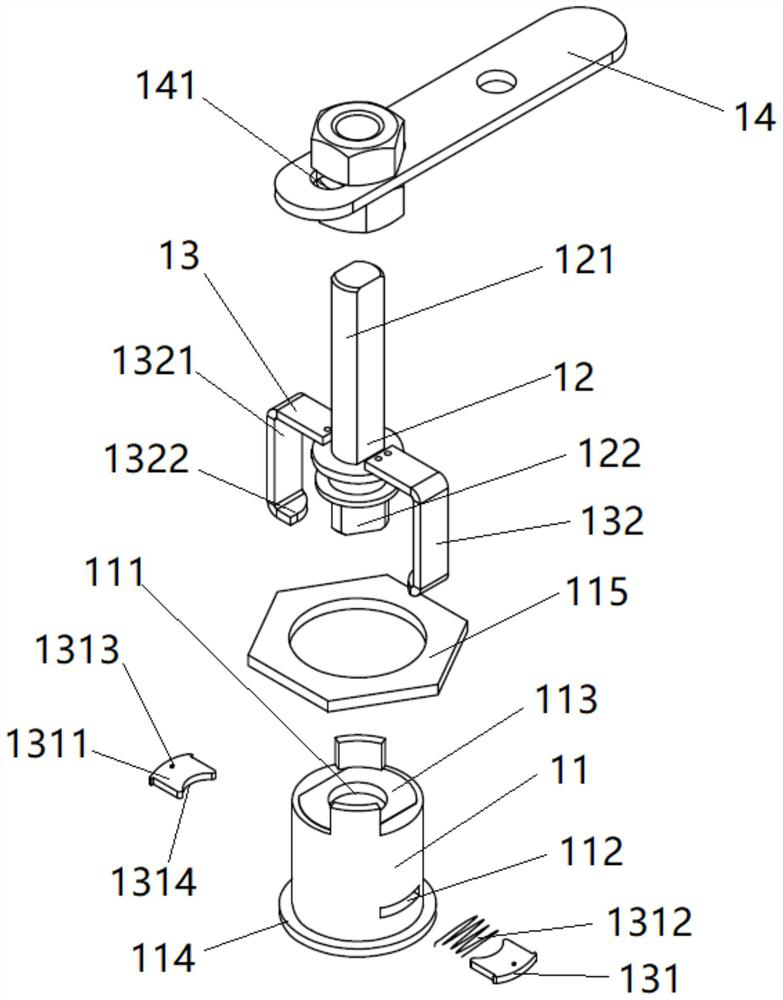
[0038] Such as figure 1 , figure 2 , Figure 4 and Figure 5 As shown, the present embodiment provides a triangular lock device, which is composed of a lock 1 and a key 2 . Wherein the lockset 1 comprises a lock body 11, a lock core 12 and an anti-off mechanism 13; the lock body 11 is provided with a lock hole 111 through which two ends pass through, and one end of the lock core 12 with a triangular head 122 is rotatably arranged in the lock hole 111, After the key 2 is inserted into the lock hole 111 , the triangular groove on the key 2 can cooperate with the triangular head 122 on the lock cylinder 12 . The anti-off mechanism 13 is composed of a card puller 132 installed on the lock core 12 and an elastic clip 131 arranged on the lock body 11. The side wall of the lock body 11 is provided with a through groove 112 communicating with the lock hole 111, and the elastic clip Part 131 is telescopically embedded in the through groove 112, and the card puller 132 rotates sync...

Embodiment 2

[0045] Such as figure 2 , image 3 and Figure 6 As shown, on the basis of Embodiment 1, this embodiment improves the structure of the key 2 and the structure of the card 1311, so that the two are more closely matched, and the effect of the card 1311 constraining the key 2 is improved, so that the key 2 is more stably restricted. In the lock hole 111, avoid the key 2 falling off due to accidental vibration or scratching.

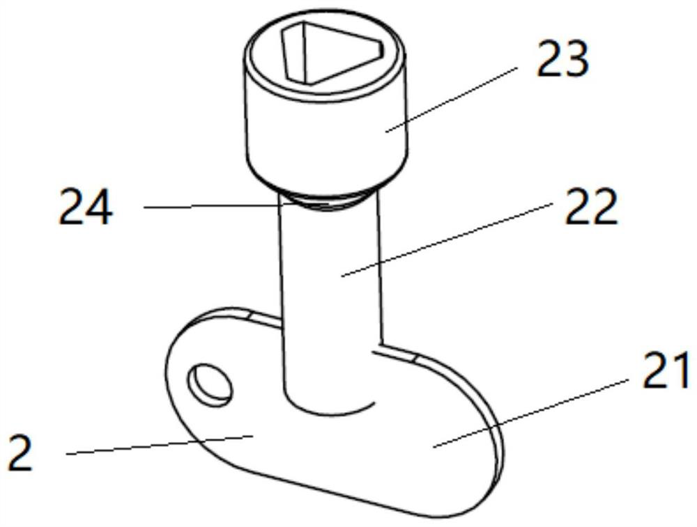
[0046] Such as image 3 and Figure 6 As shown, the key 2 is composed of a handle body 21, a rod body 22 and a fitting head 23 with a triangular groove connected in sequence, wherein the fitting head 23 and the rod body 22 are both cylinders, and the central axes of the two coincide to maintain linear alignment , the diameter of the fitting head 23 is greater than the diameter of the rod body 22, and a step-like or slope-like hoop position 24 will be formed at the junction of the two due to the size difference. After the card 1311 is pushed by the pusher ...

Embodiment 3

[0049] Such as figure 1 , figure 2 and Figure 6 As shown, in this embodiment, on the basis of embodiment 1 or embodiment 2, some structures of the lockset 1 are improved to optimize the effect of the triangular lock device.

[0050] Such as figure 2 As shown, the lock core 12 is composed of a lock bar 121 and a triangular head 122 arranged at the end of the lock bar 121; the lock bar 121 is a quadrangular prism, wherein the two opposite side walls of the lock bar 121 are planes, and the other two opposite side walls is a convex arc. The locking bar 121 can be formed by two cylinders cut by parallel planes. The side walls of the two convex arcs are provided with continuous threads for matching nuts, and the side walls of the two planes are used to provide a rotation limiting effect.

[0051] Such as figure 2 As shown, the lock 1 also includes a trigger paddle 14 , and a bar-shaped groove 141 is opened on the trigger paddle 14 . During installation, after inserting th...


PUM


Abstract

The invention discloses a triangle lock device. The triangle lock device comprises a lock and a key which are matched with each other, and the lock comprises a lock body, a lock cylinder and an anti-disengaging mechanism; and a lock hole penetrating through the two ends of the lock body is formed in the lock body, a through groove communicating with the lock hole is further formed in the side wallof the lock body, one end of the lock cylinder is rotatably embedded in the lock hole, the anti-disengaging mechanism comprises an elastic clamping piece arranged in the through groove in a telescopic mode and a pulling and clamping device fixedly installed on the lock cylinder, the pulling and clamping device pushes an elastic clamping piece along with rotation of the lock cylinder, and the elastic clamping piece extends into the lock hole to limit the key from being disengaged. According to the triangle lock device, the anti-disengaging mechanism for limiting disengaging of the key is additionally arranged, the function that the key cannot disengage in the lock opening state is achieved, and the triangle lock device can be used as a device for opening an electric trigger switch; and other locks adopted by an elevator are the same as existing triangle locks, the effect that the triangle locks on all structures of the elevator share one key is achieved, the types of keys are reduced,and the overhauling and maintaining efficiency is improved.

Description

technical field [0001] The invention belongs to the field of elevator equipment, in particular to a triangular lock device. Background technique [0002] As special equipment, elevators are required to use special triangular locks for their locks. In general, it is used in elevator landing doors, safety windows, control cabinets and other structures. However, when the triangular lock is used as a device for opening the electrical trigger switch, the functional requirements of the triangular lock are different. The key needs to be inserted into the lock hole and rotated to the position where the trigger switch is turned on, and the key should not be removed during inspection and maintenance operations, so as to prevent the trigger switch from being unable to reset due to the key being removed, thereby threatening the operation safety of the elevator. [0003] The existing triangular lock cannot provide the function of keeping the key in place. If the pin lock is used, the k...

Claims


Application Information

Patent Timeline
IPC IPC(8): E05B13/04E05B19/00E05B15/00B66B13/02
CPCB66B13/02E05B13/04E05B15/00E05B19/00
Inventor 张灵林贤庆邹玮张润祖侯应浩
Owner GUANGZHOU GUANGRI ELEVATOR IND
Why Eureka
Try Eureka