Composite rock breaking method, cutterhead and heading machine

A rock-breaking and cutter head technology, which is applied in earthwork drilling, mining equipment, tunnels, etc., can solve the problems of high installation rate, large thrust and large torque of composite rock-breaking roadheaders, etc.

Active Publication Date: 2021-02-12
CHINA RAILWAY ENGINEERING EQUIPMENT GROUP CO LTD
View PDF7 Cites 5 Cited by
  • Summary
  • Abstract
  • Description
  • Claims
  • Application Information

AI Technical Summary

Problems solved by technology

[0005] Aiming at the deficiencies in the above-mentioned background technology, the present invention proposes a composite rock-breaking method, a cutter head and a roadhe

Method used


Image

  • Composite rock breaking method, cutterhead and heading machine
  • Composite rock breaking method, cutterhead and heading machine
  • Composite rock breaking method, cutterhead and heading machine

Examples


Embodiment 1

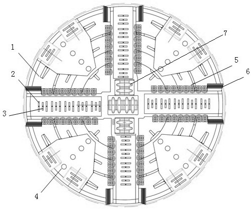
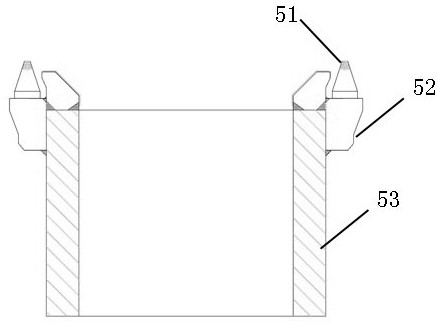
[0030] Embodiment 1, a kind of composite rock breaking method, such as Figure 4 As shown, the high-speed water jet ejected from the high-speed water jet nozzle 2 causes cracks in the rock mass; as Figure 5 As shown in , the supercritical carbon dioxide injected from the supercritical carbon dioxide nozzle is injected into the fracture; Figure 6 As shown, the microwave generating system heats the supercritical carbon dioxide in the fracture through the microwave radiating arm 4 to cause a rapid phase transition, and uses a cutter system to break the supercritical carbon dioxide in the fracture after the phase transition. First, high-speed water jets are used to create cross-cracks at a certain angle in the rock mass, and then supercritical carbon dioxide is quickly injected into the cross-cracks, and a microwave generation system is used to heat the supercritical carbon dioxide injected into the prefabricated cracks to heat up rapidly. The critical carbon dioxide rapidly un...

Embodiment 2

[0031] Embodiment 2, a composite rock-breaking method, the high-speed water jet, supercritical carbon dioxide injection into cracks, heating by microwave generation system, and rock-breaking by tool system are performed sequentially and cyclically. By maximizing the expansion of supercritical carbon dioxide in fractures created by high-velocity water jets, the cutter system can more easily break rock efficiently.

[0032] Other methods of this embodiment are the same as in Embodiment 1.

Embodiment 3

[0033] Embodiment 3, a composite rock-breaking method, the high-speed water jet, supercritical carbon dioxide injected into cracks, microwave generation system heating, and cutter system rock-breaking are carried out simultaneously, so that the cracks produced by high-speed water jet rock-breaking can be combined with supercritical carbon dioxide The blasting gas and the tool system are superimposed on rock breaking at the same time, layer by layer, to achieve the effect of efficient rock breaking.

[0034] Other methods of this embodiment are the same as in Embodiment 1.


PUM


Abstract

The invention discloses a composite rock breaking method. The method comprises the following steps of generating a crack in a rock body by adopting high-speed water jetting, jetting supercritical carbon dioxide into the crack, heating the supercritical carbon dioxide in the crack by adopting a microwave generation system so as to achieve the rapid phase change of the supercritical carbon dioxide,and breaking the rock body subjected to phase change of the supercritical carbon dioxide in the crack by adopting a cutter system. The invention further discloses a composite rock breaking cutterhead.The composite rock breaking cutterhead comprises a cutterhead panel, the cutter system and a high-speed water jet system are arranged on the cutterhead panel, and a supercritical carbon dioxide jet system and the microwave generation system are arranged on the cutterhead panel. The invention further discloses a composite rock breaking heading machine. The composite rock breaking heading machine comprises a cutterhead which is the same as the composite rock breaking cutterhead. According to the composite rock breaking method, cutterhead and heading machine, the technical problems that an existing composite rock breaking heading machine is large in thrust, large in torque, high in loading efficiency and serious in cutter abrasion.

Description

technical field [0001] The invention relates to the technical field of rock breaking in hard rock tunnel excavation, in particular to a composite rock breaking method, a cutterhead and a roadheader. Background technique [0002] In the field test and research process of tunnel excavation, for superhard rock (generally saturated uniaxial compressive strength ≥ 200MPa) in tunnel engineering, the existing hob is not easy to cause through-cracks in the rock mass during the rock breaking process, such as figure 1 As shown, the rock breaking efficiency is not high, and the hob 8 is seriously worn, which greatly reduces the construction efficiency and increases the construction cost. Moreover, the jacking force and torque of the existing hard rock TBM hob for rock breaking are large, resulting in a large installed power of the whole equipment and huge equipment costs. At the same time, the high installed power leads to a huge high electricity cost for the equipment. [0003] In o...

Claims


Application Information

Patent Timeline
IPC IPC(8): E21D9/10E21D9/11
CPCE21D9/1066E21D9/1073E21D9/11E21D9/006
Inventor 鲁义强李光贺飞庞培彦杨承璋
Owner CHINA RAILWAY ENGINEERING EQUIPMENT GROUP CO LTD
Why Eureka
Try Eureka