Lining concrete watering maintenance equipment for tunnel construction
A technology for tunnel construction and concrete, which is applied in the direction of tunnel lining, tunnel lining, shaft lining, etc. It can solve the problems of inconvenient water spray maintenance for tunnels and difficult water spray on the inner wall of tunnels, etc., and achieves the effects of increased area, high work efficiency, and accelerated hardening
- Summary
- Abstract
- Description
- Claims
- Application Information
AI Technical Summary
Problems solved by technology
Method used
Image

Examples
Embodiment 1
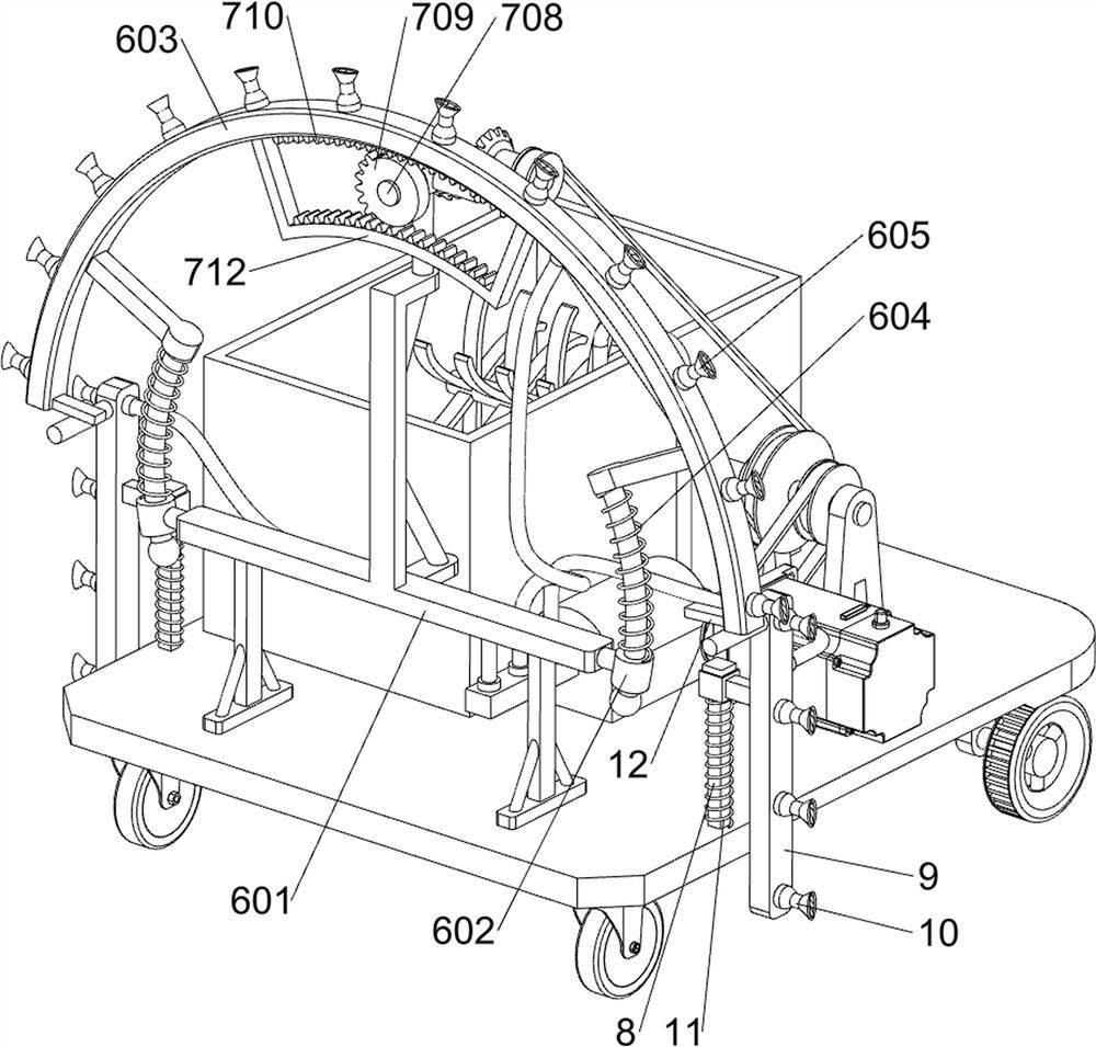
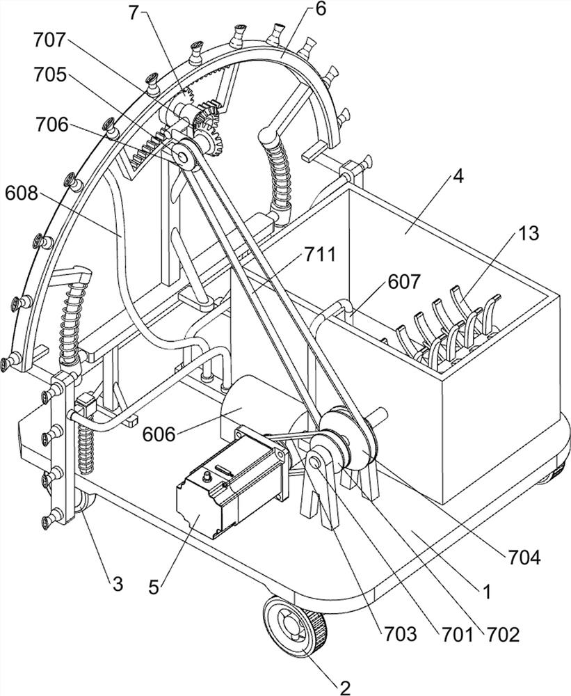
[0016] A lining concrete sprinkler maintenance equipment for tunnel construction, such as Figure 1-2 As shown, it includes a bottom plate 1, a roller 2, a universal wheel 3, a water storage tank 4, a servo motor 5, a sprinkler assembly 6 and a swing assembly 7. The side-to-back symmetrical rotation type is equipped with universal wheels 3, the top right and rear side of the bottom plate 1 is connected with a water storage tank 4 by bolts, the servo motor 5 is installed in the middle of the front side of the top of the bottom plate 1, and the sprinkler assembly 6 is installed on the left side of the top of the bottom plate 1. 1 and the output shaft of the servo motor 5 is provided with a swing assembly 7.
[0017] The sprinkler assembly 6 includes a support frame 601, a guide sleeve 602, a first shunt pipe 603, a first spring 604, a first nozzle 605, a water pump 606, a water inlet pipe 607 and a water outlet pipe 608, and the top left side of the bottom plate 1 is fixedly con...
Embodiment 2
[0023] On the basis of Example 1, such as Figure 1-2As shown, it also includes a guide rod 8, a second shunt pipe 9, a second nozzle 10, a second spring 11 and a contact block 12. The left side of the top of the bottom plate 1 is fixedly connected with a guide rod 8 symmetrically front and back, and the guide rod 8 slides The second distribution pipe 9 is provided with a plurality of second nozzles 10 evenly spaced on the second distribution pipe 9, and the second distribution pipes 9 are connected to the water outlet pipe 608, and the second distribution pipes 9 are connected to the bottom plate 1. There is a second spring 11, and the second spring 11 is set on the guide rod 8. The bottoms of the front and rear sides of the first shunt pipe 603 are fixedly connected with contact blocks 12, and the contact blocks 12 are matched with the corresponding second shunt pipes 9.
[0024] It also includes a stirring rod 13 , the rear end of the first rotating shaft 701 passes through...
PUM
 Abstract
Description
Claims
Application Information