Supercharge Your Innovation With Domain-Expert AI Agents!

Temperature difference detection circuit used for over-temperature protection

A technology of temperature detection circuit and detection circuit, which is applied in the direction of emergency protection circuit device, emergency protection detection, circuit device, etc., can solve the problems of inability to compare the temperature difference of the chip heating point, chip thermal damage, and inability to realize over-temperature difference protection, etc.

Active Publication Date: 2021-02-12
SMART SHINE MICROELECTRONICS TECH CO LTD
View PDF12 Cites 0 Cited by
  • Summary
  • Abstract
  • Description
  • Claims
  • Application Information

AI Technical Summary

Problems solved by technology

Existing over-temperature protection circuits usually can only detect the temperature of one heating point in the chip, and cannot compare the temperature difference of different heating points in the chip. Only when the temperature of the detected heating point reaches the set value, it will trigger and work. Over-temperature protection cannot be realized; however, at this time, the temperature of the heat-generating points in different parts of the chip is inconsistent, and other heat-generating points are overheated (exceeding the set value) and cannot trigger the over-temperature protection, which will cause the chip to be thermally damaged

Method used


Image

  • Temperature difference detection circuit used for over-temperature protection
  • Temperature difference detection circuit used for over-temperature protection
  • Temperature difference detection circuit used for over-temperature protection

Examples


Embodiment 1

[0026] This embodiment provides a temperature difference detection circuit for over-temperature protection, including a temperature detection circuit and a temperature difference comparison circuit; the temperature detection circuit is used to detect the temperature of the first detection point; the temperature difference comparison circuit is used to detect the temperature of the second detecting the temperature at the point and comparing the temperature at the second detecting point with the temperature at the first detecting point to obtain a temperature difference between the second detecting point and the first detecting point.

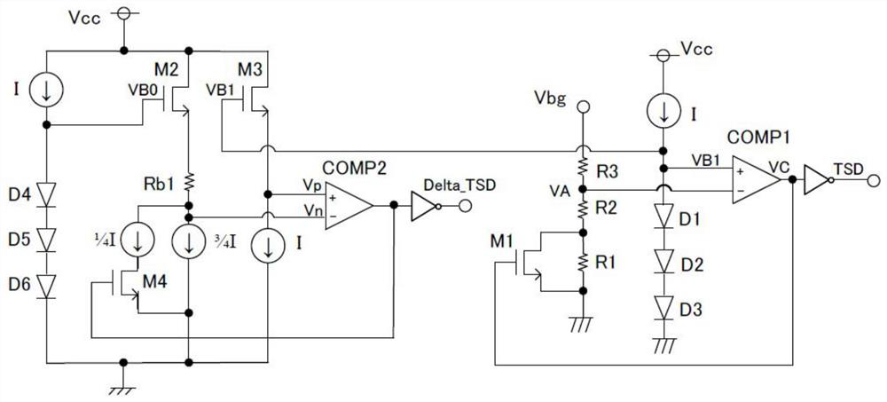
[0027] figure 1 It is a circuit diagram of a temperature difference detection circuit for over-temperature protection provided by Embodiment 1 of the present invention. Such as figure 1 As shown, the temperature detection circuit of this embodiment includes a first diode assembly, a first comparator COMP1 and a first MOS transistor M1. The anod...

Embodiment 2

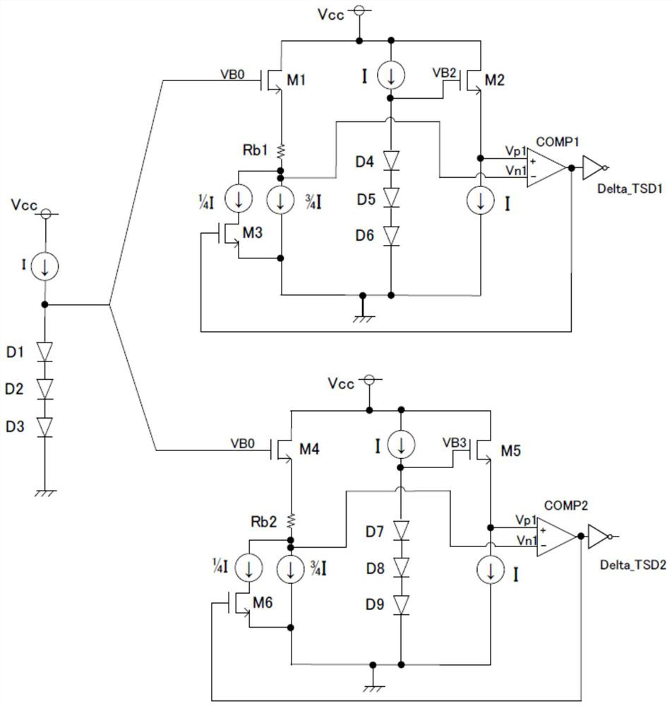
[0044] This embodiment provides a temperature difference detection circuit for over-temperature protection, including a temperature detection circuit and a temperature difference comparison circuit; the temperature detection circuit is used to detect the temperature of a reference point; the temperature difference comparison circuit includes a first temperature difference comparison circuit and a temperature difference comparison circuit. The second temperature difference comparison circuit; the first temperature difference comparison circuit is used to detect the temperature of the first detection point and compare the temperature of the first detection point with the temperature of the reference point to obtain the first detection point and the temperature of the reference point The temperature difference of the reference point; the second temperature difference comparison circuit is used to detect the temperature of the second detection point and compare the temperature of th...


PUM


Abstract

The invention belongs to the technical field of integrated circuits and provides a temperature difference detection circuit for over-temperature protection. The circuit comprises a temperature detection circuit and a temperature difference comparison circuit; the temperature detection circuit is used for detecting the temperature of a first detection point; and the temperature difference comparison circuit is used for detecting the temperature of a second detection point and comparing the temperature of the second detection point with the temperature of the first detection point to obtain thetemperature difference between the second detection point and the first detection point. According to the temperature difference detection circuit used for the over-temperature protection of the invention, over-temperature protection and over-temperature difference protection of two or more heating points can be realized.

Description

technical field [0001] The invention relates to the technical field of integrated circuits, in particular to a temperature difference detection circuit for over-temperature protection. Background technique [0002] As the chip integration becomes higher and higher, the performance is better and better, and the power consumption is larger and larger, so that the temperature of the chip will rise rapidly when the integrated circuit is used for a long time or under abnormal conditions such as short circuit. High temperature will affect the stability of the chip. Overheating will cause the chip to fail to work normally or even damage its electronic components. Over-temperature protection is especially important in high-performance integrated circuits. [0003] In the power switch chip, due to the complex application scenarios, the power switch load may be short-circuited, and the power supply voltage will be directly connected to the turned-on power switch, and the instantaneous...

Claims


Application Information

Patent Timeline
Patent Type & Authority Applications(China)
IPC IPC(8): G01K3/14H02H1/00H02H5/04
CPCG01K3/14H02H1/0007H02H5/04H02H5/044Y02E60/10
Inventor 王永刚
Owner SMART SHINE MICROELECTRONICS TECH CO LTD
Features
  • R&D
  • Intellectual Property
  • Life Sciences
  • Materials
  • Tech Scout
  • Unparalleled Data Quality
  • Higher Quality Content
  • 60% Fewer Hallucinations
Learn More