
Indoor micro differential pressure sensor sampling mounting head

A micro differential pressure sensor and sampling tube technology, which is used in sampling devices, pressure difference measurement between multiple valves, sampling, etc. problem, to achieve the effect of enhancing sampling stability, improving measurement accuracy, and improving measurement accuracy

Pending Publication Date: 2021-02-12
CHINA ELECTRONICS SYST ENG NO 2 CONSTR
View PDF0 Cites 1 Cited by
  • Summary
  • Abstract
  • Description
  • Claims
  • Application Information

AI Technical Summary

Problems solved by technology

[0003] The micro-pressure difference sensor is connected to the sampling head through a hose, and the sampling head is fixed on the ceiling of the factory building, and the existing sampling head has many shortcomings that need to be improved urgently. The traditional sampling head is made of plastic, and the cost is lower than that of stainless steel. The head is relatively low, but the sampling head made of plastic is easy to be damaged. Long-term use will cause dust and debris, which will affect the cleanliness of the fan filter purification plant, and the final indirect economic loss will be compared with the production of sampling devices made of stainless steel. The cost of the head is high, and it is not easy to use a plastic sampling head in the fan filter purification plant, and the sampling point at the end of the sampling head of the traditional sampling head is single-hole collection, which is greatly affected by the air flow in the plant, resulting in inaccurate measurement At the same time, the traditional sampling head is fixed by glue, and the glue loses its viscosity after a long time, which makes the fixing of the sampling head unreliable, and the glue affects the appearance of the sampling head. The above shortcomings are not suitable for building a clean operation in the factory surroundings

Method used


Image

  • Indoor micro differential pressure sensor sampling mounting head
  • Indoor micro differential pressure sensor sampling mounting head
  • Indoor micro differential pressure sensor sampling mounting head

Examples


specific Embodiment approach

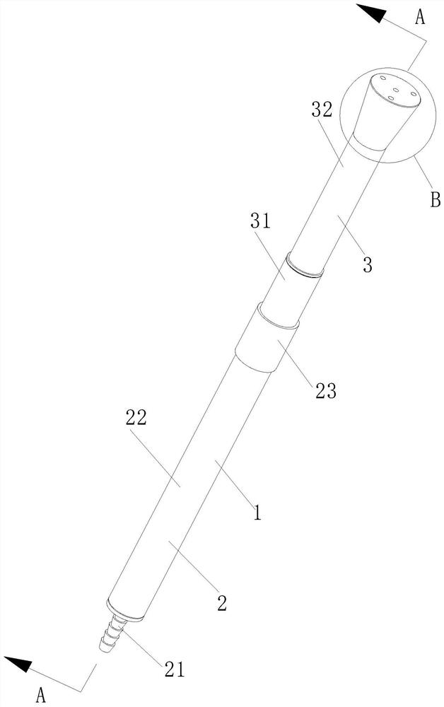
[0022] As a specific embodiment of the present invention, the conduction part 2 includes a hexagonal pagoda joint 21, an extension pipe 22 and a No. 1 adapter 23; the hexagonal pagoda joint 21 communicates with the hose on the external micro-pressure differential sensor, and the hexagonal pagoda The joint 21 is threadedly connected to the extension pipe 22, and the hexagonal pagoda joint 21 can be selected with an internal thread with a nominal diameter of 15MM; the extension pipe 22 is threadedly connected to the No. A double-headed outer thread pipe with a diameter of 20MM, and an extension tube 22 is selected according to the installation length of the body 1; the No. 1 adapter 23 is threaded to connect the collection part 3, and the No. 1 adapter 23 can be selected with a nominal diameter of 20MM with a length of 35mm The double-headed inner wire pipeline of the No. 1 adapter 23 is more suitable for the thickness of the existing ceiling, which is convenient for the fixing o...


PUM

PropertyMeasurementUnit
thicknessaaaaaaaaaa
lengthaaaaaaaaaa
diameteraaaaaaaaaa

Abstract

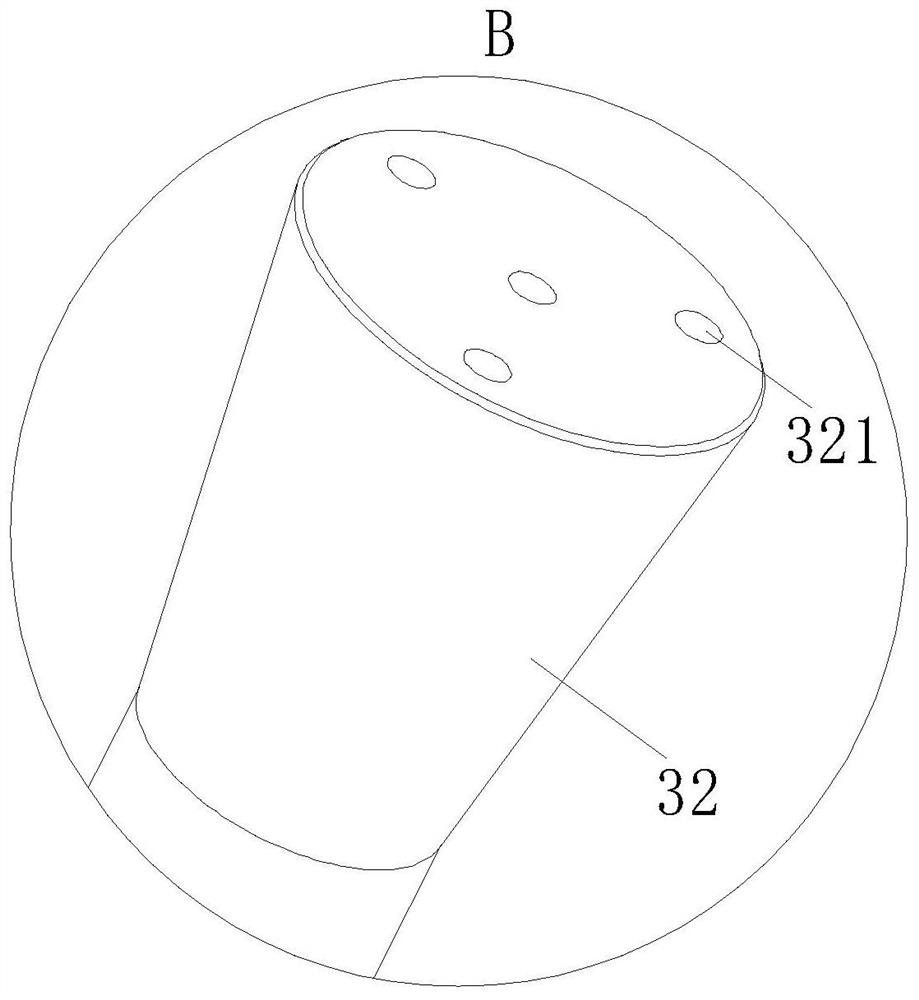
The invention belongs to the technical field of clean workshop differential pressure control, and particularly relates to an indoor micro differential pressure sensor sampling mounting head which comprises a sampling mounting head body, and the body comprises a conduction part and an acquisition part; the conduction part is in threaded connection with the collection part, the conduction part is arranged above a ceiling in a purification workshop room of the fan filter, the collection part is arranged below the ceiling in the purification workshop room of the fan filter, and the conduction partand the collection part are both made of stainless steel materials; compared with a plastic material body, the stainless steel material body has the advantages of being longer in service life and notprone to aging, dust generation and chipping falling, the sampling head adopts the porous collection design, it is guaranteed that a source taking point is stable, higher anti-interference capacity is achieved, and benefits of manufacturers are better facilitated from the aspects of cost and later-period maintenance.

Description

technical field [0001] The invention belongs to the technical field of differential pressure control in clean workshops, in particular to a sampling head for an indoor micro-pressure differential sensor. Background technique [0002] The micro-pressure differential sensor is a product based on the mechanical micro-pressure differential gauge and the mechanical micro-pressure differential function. The mechanical pointer micro-pressure differential gauge only has the pointer display function, and the mechanical differential pressure gauge can only realize the change of gas pressure in an invisible environment. Alarm or general control, mechanical products have the characteristics of rough measurement and mechanical transmission, and the gas micro pressure difference sensor is controlled by an electronic chip to realize the core unit of digital visualization, high-precision measurement, big data processing and other characteristics to meet the modern intelligent centralized con...

Claims


Application Information

Patent Timeline
Patent Type & Authority Applications(China)
IPC IPC(8): G01L13/00G01N1/22
CPCG01L13/00G01N1/2205
Inventor 张小敏胡昌军白振良陈卫军金才龙季庆雯
Owner CHINA ELECTRONICS SYST ENG NO 2 CONSTR
Learn More