
Motor rotor, motor and installation method of motor rotor

A technology for motor rotors and installation methods, which is applied in the direction of electromechanical devices, manufacturing motor generators, manufacturing stator/rotor bodies, etc., can solve the problems of high cost of rotor cores, easy bolts to fall off, etc., to save processing costs, reduce losses, The effect of enhancing reliability

Active Publication Date: 2021-02-12
SHANGHAI ELECTRIC WIND POWER GRP CO LTD
View PDF11 Cites 0 Cited by
  • Summary
  • Abstract
  • Description
  • Claims
  • Application Information

AI Technical Summary

Problems solved by technology

[0003] The technical problem to be solved by the present invention is to provide a motor rotor, a motor and a method for installing the motor rotor in order to overcome the high cost of installing the rotor core in the motor rotor and the defects that the bolts are easy to fall off in the prior art

Method used


Image

  • Motor rotor, motor and installation method of motor rotor
  • Motor rotor, motor and installation method of motor rotor
  • Motor rotor, motor and installation method of motor rotor

Examples


Embodiment Construction

[0072] The present invention will be further described below by means of specific examples, but the present invention is not limited to the scope of the following examples.

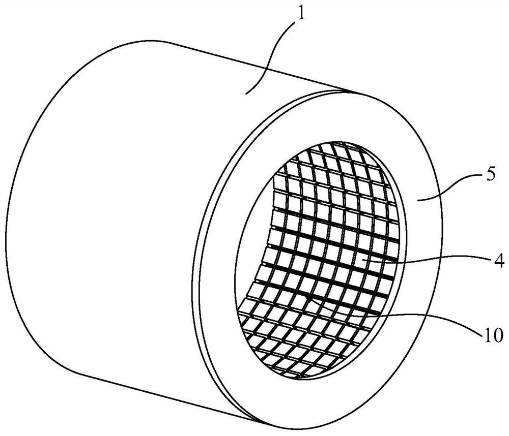
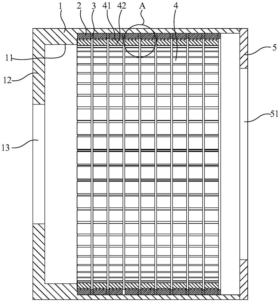
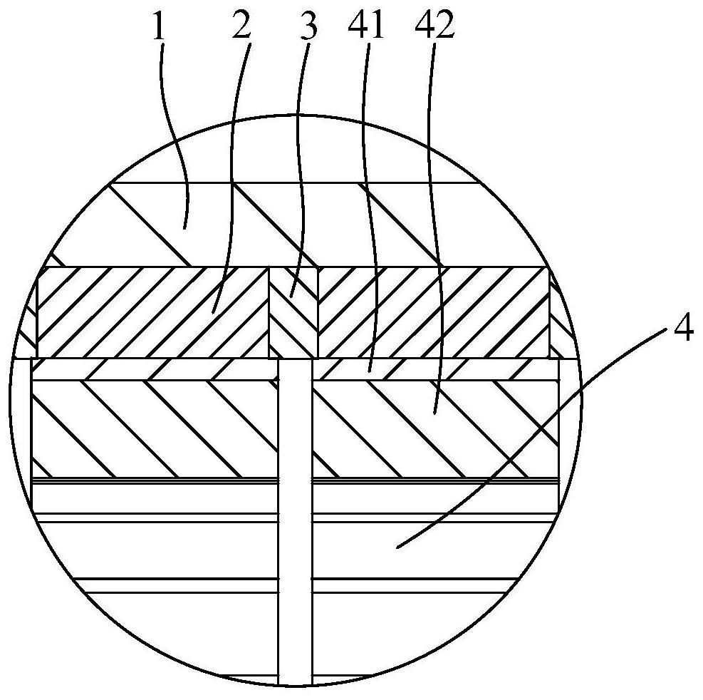
[0073] Such as Figure 1-5 As shown, it is a motor rotor of this embodiment, including a rotor house 1. There is a cylindrical cavity 10 extending axially along the rotor house 1 inside the rotor house 1. The end of the rotor house 1 has a hole communicating with the cylindrical cavity 10. Opening, the motor rotor also includes a plurality of rotor cores 2 and a plurality of bridging ribs 3, the rotor cores 2 and bridging ribs 3 are ring structures, and the outer peripheral surface of the rotor core 2 and the outer peripheral surface of the bridging ribs 3 All are attached to the inner peripheral surface of the cylindrical cavity 10; multiple rotor cores 2 and multiple bridging ribs 3 are arranged at intervals along the axial direction of the cylindrical cavity 10, and the sides of the bridging ribs 3 pre...


PUM


Abstract

The invention discloses a motor rotor, a motor and a mounting method of the motor rotor. The motor rotor comprises a rotor room, and a cylindrical cavity extending in the axial direction of the rotorroom is arranged in the rotor room; the motor rotor is characterized by further comprising a plurality of rotor cores and a plurality of bridging rib plates, the rotor cores and the bridging rib plates are annular structures; the outer peripheral surface of the rotor core and the outer peripheral surfaces of the bridging rib plates are attached to the inner peripheral surface of the cylindrical cavity; the multiple rotor cores and the multiple bridging rib plates are arranged at intervals in the axial direction of the cylindrical cavity, the side faces of the bridging rib plates abut against the rotor cores on the same side, and the bridging rib plates are fixed in the cylindrical cavity through welding. According to the motor rotor, the risk caused by bolt loosening is avoided, and the reliability of the rotor core is enhanced. The outer peripheral surface of the rotor core can be completely attached to the inner peripheral surface of the rotor house, the structural integrity is verygood, and the risk of local tiny vibration is reduced.

Description

technical field [0001] The invention relates to the field of motors, in particular to a motor rotor, a motor and a method for installing the motor rotor. Background technique [0002] The permanent magnet motor provides a magnetic field by installing multiple sets of permanent magnet modules on the inner wall of the outer rotor as its magnetic poles. In order to reduce the various corrosions of the permanent magnets and improve the efficiency and life of the permanent magnets, the permanent magnets are usually packaged and made into magnetic pole modules. In existing permanent magnet motors, in order to reduce power loss, a rotor core is usually provided between the inner wall of the outer rotor and the magnetic pole module. The rotor core is generally a laminated silicon steel sheet. Due to the large size of the outer rotor of a large motor, the required rotor core is relatively large in size and heavy in weight. Generally, it is fixed by opening dovetail grooves on the in...

Claims


Application Information

Patent Timeline
IPC IPC(8): H02K1/28H02K1/27H02K15/02H02K15/03
CPCH02K1/27H02K1/28H02K15/02H02K15/03
Inventor 王江乔
Owner SHANGHAI ELECTRIC WIND POWER GRP CO LTD
Features
  • Generate Ideas
  • Intellectual Property
  • Life Sciences
  • Materials
  • Tech Scout
  • Unparalleled Data Quality
  • Higher Quality Content
  • 60% Fewer Hallucinations
Learn More