Irrigation equipment for municipal garden maintenance

A garden and municipal technology, applied in the field of irrigation devices, can solve problems such as failure to achieve efficient utilization of resources, and achieve the effect of reducing wear and increasing service life

Active Publication Date: 2021-02-19
HUAIHUA UNIV
View PDF7 Cites 0 Cited by
  • Summary
  • Abstract
  • Description
  • Claims
  • Application Information

AI Technical Summary

Problems solved by technology

[0003] At present, in the process of irrigating green plants in the process of municipal garden maintenance, the nearby river water is used for irrigation, but the aquatic plants and impurities extracted from the river water cannot be processed by existing irrigation equipment, and the aquatic plants and impurities are all filtered through the filter structure. Filtering out fails to achieve efficient use of resources, so the water plants are filtered o

Method used


Image

  • Irrigation equipment for municipal garden maintenance
  • Irrigation equipment for municipal garden maintenance
  • Irrigation equipment for municipal garden maintenance

Examples


Embodiment 1

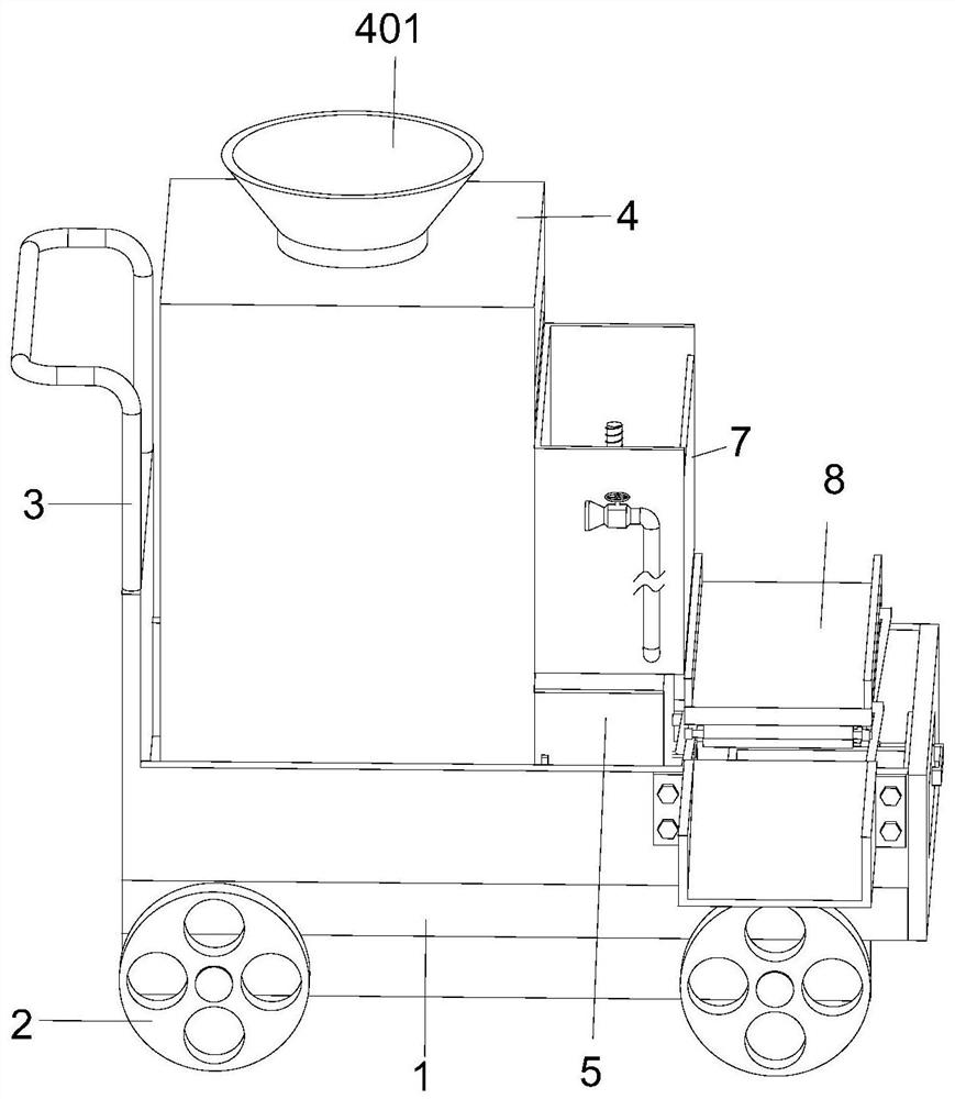
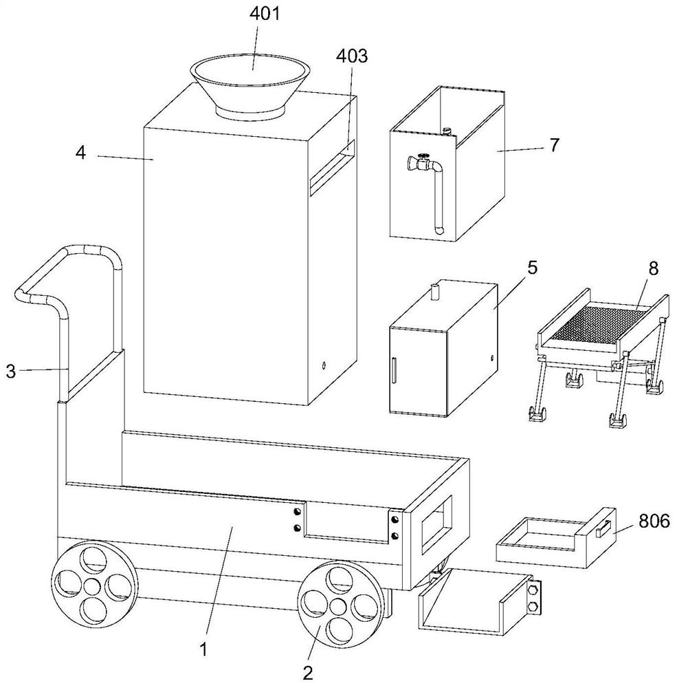
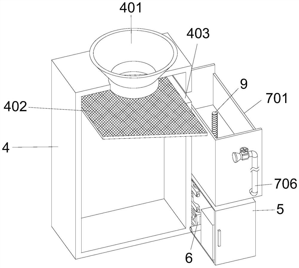
[0031] see Figure 1-4 , a kind of irrigation equipment for municipal garden maintenance, comprising a car body 1, two wheels 2 are arranged on the bottom of the front and rear sides of the car body 1, a handrail 3 is provided on the top of the rear end of the car body 1, and a Water tank 4, the top surface of water tank 4 is provided with water tank 401, and the inside of water tank 4 is left high with respect to the position below water tank 401 and right bottom structure is fixedly provided with filter screen 402, and the position of water tank 4 right end is provided with relative to the position of filter screen 402 right end A filter tank 403, a power box 5 is provided at the bottom of the right end of the water tank 4, a power assembly 6 is provided inside the power box 5, a garbage disposal module 7 is provided at the right end of the water tank 4 relative to the position below the filter tank 403, and a right end top surface of the vehicle body 1 is provided with Shak...

Embodiment 2

[0035] see Figure 4-5The difference in the basis of Embodiment 1 is that the garbage disposal module 7 includes a garbage bin 701, the garbage bin 701 is fixed at the position below the filter tank 403, and the middle part of the bottom end of the garbage bin 701 is fixed with a water pressure box 702 , the water pressure box 702 is set in a hollow cylindrical structure, the inside of the water pressure box 702 is provided with a rotating seat 703, and the outer wall of the rotating seat 703 is annular and equidistantly fixed with a plurality of water baffles 704, and the front and rear ends of the water pressure box 702 Two drainage holes 705 are symmetrically opened in the center. The drainage holes 705 are internally connected with a drainage pipe 706. A rotary box 707 is fixed in the middle of the top surface of the water pressure box 702. A coil spring 708 is fixed on the inner wall of the rotary box 707. Above the rotary box 707 A pallet 709 is provided.

[0036] The g...

Embodiment 3

[0039] see Figure 6 , the difference between the foundations of Embodiments 1 and 2 is that the water inlet pipe of the booster pump 601 extends to the inside of the water tank 4, and the drain pipe 706 on the rear side extends through the bottom surface of the dustbin 701 to the inside of the power box 5 and is connected with the booster pump. The water outlet of the pressure pump 601 is connected and fixed, and the drain pipe 706 at the front side extends through the front end of the dustbin 701 to its front side.

[0040] The vibrating screen module 8 includes a vibrating screen plate 801 located at the lower left side of the dustbin 701. The vibrating screen plate 801 is arranged in an inclined structure with a rear height and a front bottom. Two hinge seats 802 are provided, and the hinge seats 802 are rotationally connected with the vibrating screen plate 801 through connecting rods. The front bottom surface of the vibrating screen plate 801 is provided with a rotating ...


PUM


Abstract

The invention discloses irrigation equipment for municipal garden maintenance, and belongs to the technical field of irrigation devices. The irrigation equipment for municipal garden maintenance comprises a vehicle body, a water tank is fixedly arranged on the top face of the right end of the vehicle body, a water adding groove is formed in the top face of the water tank, a filter screen is fixedly arranged at the position, corresponding to the position below the water adding groove, in the water tank in a left-high right-bottom structure, and a filter groove is formed in the position, corresponding to the right end of the filter screen, in the right end of the water tank; and a power box is arranged at the bottom of the right end of the water tank, a power assembly is arranged in the power box, a garbage treatment module is arranged at the position, corresponding to the position below the filtering groove, at the right end of the water tank, and a vibration screening module is arranged on the top face of the right end of the vehicle body. According to the irrigation equipment, the garbage treatment module is arranged at the right end of the water tank and comprises a garbage can used for containing filtered aquatic plants, when a booster pump is used for irrigation, water flow passes through a water pressure box, a threaded rod can rotate, and a supporting plate moves upwardsthrough the threaded rod to discharge the aquatic plants.

Description

technical field [0001] The invention relates to the technical field of irrigation devices, in particular to irrigation equipment for municipal garden maintenance. Background technique [0002] Greening maintenance, that is, watering, pruning, weeding, spraying, and seedling replenishment after completing the greening construction are collectively referred to as maintenance. The work is simple, but essential, and very important. In the process of rapid urbanization, the development of municipal greening construction is also in full swing. [0003] At present, in the process of irrigating green plants in the process of municipal garden maintenance, the nearby river water is used for irrigation, but the aquatic plants and impurities extracted from the river water cannot be processed by existing irrigation equipment, and the aquatic plants and impurities are all filtered through the filter structure. Filtering out fails to achieve efficient use of resources, so the water plants...

Claims


Application Information

Patent Timeline
IPC IPC(8): A01G25/09B01D29/03B01D29/76
CPCA01G25/09B01D29/03B01D29/76
Inventor 吴曼颖
Owner HUAIHUA UNIV
Why Eureka
Try Eureka