
Servo motor shell end cover manufacturing and stamping method

A servo motor and shell end technology, which is applied in the field of servo motor shell end cover manufacturing, can solve the problems of increased employee workload, insufficient punching, cost waste, etc., to avoid insufficient punching, improve forming rate, and waste manpower Effect

Inactive Publication Date: 2021-02-19
吴振飞
View PDF0 Cites 2 Cited by
  • Summary
  • Abstract
  • Description
  • Claims
  • Application Information

AI Technical Summary

Problems solved by technology

[0003] The existing servo motor housing end cover often has the following problems when performing hole processing: a: When the existing servo motor housing end cover is performing hole processing, it often occurs that the hole diameter is too large, resulting in insufficient punching If the situation occurs, it is necessary to manually carry out secondary selection, and perform secondary punching on the end cover of the servo motor shell with incomplete punching, which greatly increases the workload of the employees and wastes manpower; b: the existing servo motor shell end When the cover is opened, a large amount of metal waste is often generated, which is cumbersome to clean up and easily wastes cost

Method used


Image

  • Servo motor shell end cover manufacturing and stamping method
  • Servo motor shell end cover manufacturing and stamping method
  • Servo motor shell end cover manufacturing and stamping method

Examples


Embodiment Construction

[0029] The embodiments of the present invention will be described in detail below with reference to the accompanying drawings, but the present invention can be implemented in many different ways defined and covered by the claims.

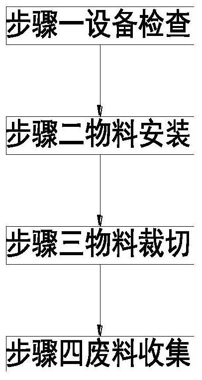
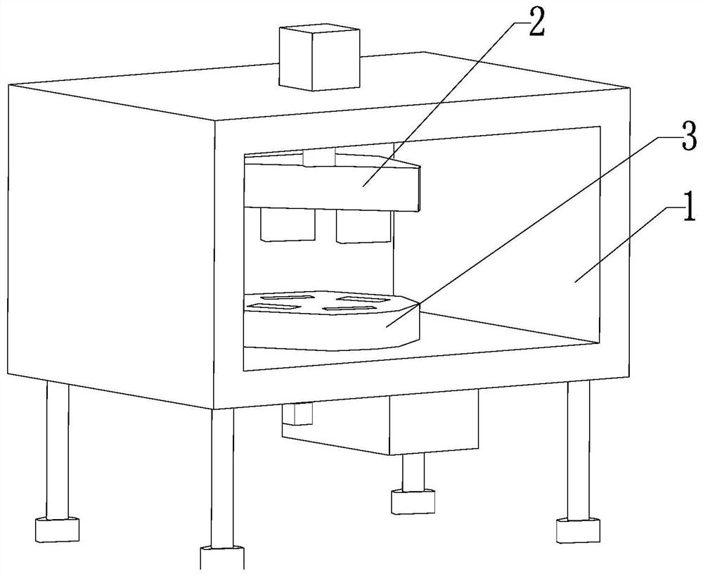
[0030] Such as Figure 1 to Figure 6 As shown, a stamping method for manufacturing an end cover of a servo motor housing mainly includes the following steps:

[0031] Step 1: Equipment inspection: Check the operation of the equipment before using the servo motor shell end cover punching device to punch the surface of the servo motor shell end cover;

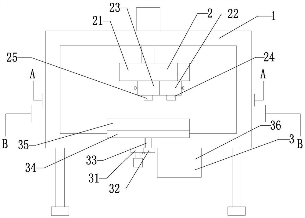
[0032] Step 2: Material installation: Manually place the end cover of the servo motor shell that needs to be punched on the loading plate 35, and the loading plate 35 works to fix the end cover of the servo motor shell, so as to achieve the purpose of material installation;

[0033] Step 3: Material cutting: After completing the material installation operation in Step 2, the No. 2 motor works, and the...


PUM


Abstract

The invention relates to a servo motor shell end cover manufacturing and stamping method. The servo motor shell end cover manufacturing and stamping method mainly comprises the following steps of equipment inspection, material mounting and material cutting and waste collection; a mounting frame, a punching external member and a fixing external member are mounted on a servo motor shell end cover stamping and forming device; and the punching external member and the fixing external member are sequentially arranged in the mounting frame from top to bottom. The servo motor shell end cover manufacturing and stamping method can solve the following problems during punching treatment of an existing servo motor shell end cover: a, during punching treatment of the existing servo motor shell end cover, the situation that punching is insufficient due to the fact that the hole diameter is too large often occurs, so that manual secondary selection is needed; and as secondary punching is carried out on the incompletely punched servo motor shell end cover, the workload of staff is greatly increased, and manpower is wasted; and b, during punching treatment of the existing servo motor shell end cover, a large amount of metal waste is often generated, so that cleaning is tedious, and cost waste is caused easily.

Description

technical field [0001] The invention relates to the technical field of manufacturing an end cover of a servo motor shell, in particular to a stamping method for manufacturing an end cover of a servo motor shell. Background technique [0002] Servo motor refers to the engine that controls the operation of mechanical components in the servo system. It is an auxiliary motor indirect transmission device. The servo motor can control the speed and position accuracy very accurately. It can convert the voltage signal into torque and speed to drive the control object. , the rotor speed of the servo motor is controlled by the input signal, and can respond quickly. In the automatic control system, it is used as an actuator, and has the characteristics of small electromechanical time constant, high linearity, and starting voltage. The signal is converted into angular displacement or angular velocity output on the motor shaft. Its main feature is that when the signal voltage is zero, the...

Claims


Application Information

Patent Timeline
Patent Type & Authority Applications(China)
IPC IPC(8): B21D28/10B21D28/12B21D28/24B21D43/20
CPCB21D28/10B21D28/12B21D28/243B21D43/20
Inventor 吴振飞廉静
Owner 吴振飞
Learn More