Heating protection suction nozzle for wafer repair machine
A heating protection and repair technology, applied in metal processing equipment, auxiliary devices, manufacturing tools, etc., can solve the problems of wafer damage, low efficiency, lack of protective gas, etc.
- Summary
- Abstract
- Description
- Claims
- Application Information
AI Technical Summary
Problems solved by technology
Method used
Image


Examples
Embodiment Construction
[0018] The present invention will be further described below in conjunction with the description of the drawings and specific embodiments.
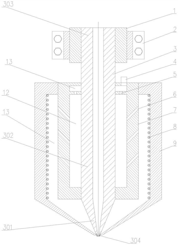
[0019] Such as Figure 1 to Figure 2 As shown, a heating protection nozzle for a wafer rework machine includes a microporous nozzle 3 with a diversion groove, a temperature sensor 10, a heating device 8 and a protective gas circulation device, the temperature sensor 10, the heating device 8. The protective gas circulation device is respectively fixed on the microporous suction nozzle 3 with diversion groove, and the microporous nozzle 3 with diversion groove is divided into a head 301, a body 302 and a tail 303 from bottom to top , the head of the microporous nozzle 3 with diversion grooves is provided with an adsorption hole 304 for absorbing wafers, and the temperature sensor 10 is located at the head 301 of the micropore nozzle 3 with diversion grooves.
[0020] The microporous suction nozzle 3 with diversion grooves is connected with...
PUM
 Abstract
Description
Claims
Application Information
PatSnap Eureka turns technology decisions into work you can execute. Powered by our Innovation Knowledge Graph, it runs expert workflows across engineering, life sciences, materials and intellectual property. Get your review-ready output in minutes.


