Machining waste material collecting device

A waste material and collection device technology, applied in the direction of metal processing equipment, metal processing machinery parts, manufacturing tools, etc., can solve the problems of poor buffer protection effect, achieve good elasticity, avoid self-structural damage, and avoid leakage

Active Publication Date: 2021-02-19
嘉兴沃瑞科技有限公司
View PDF3 Cites 0 Cited by
  • Summary
  • Abstract
  • Description
  • Claims
  • Application Information

AI Technical Summary

Problems solved by technology

[0004] The purpose of the present invention is to provide a mechanical processing waste material collection device to solve the problem that the existing waste material collection equipment has poor buffer protection effect when collecting waste materials

Method used


Image

  • Machining waste material collecting device
  • Machining waste material collecting device
  • Machining waste material collecting device

Examples


Embodiment

[0092]In order to make it easy to understand the technical means, creative features, objectives and effects achieved by the present invention, the present invention will be further explained below in conjunction with the drawings and specific embodiments.

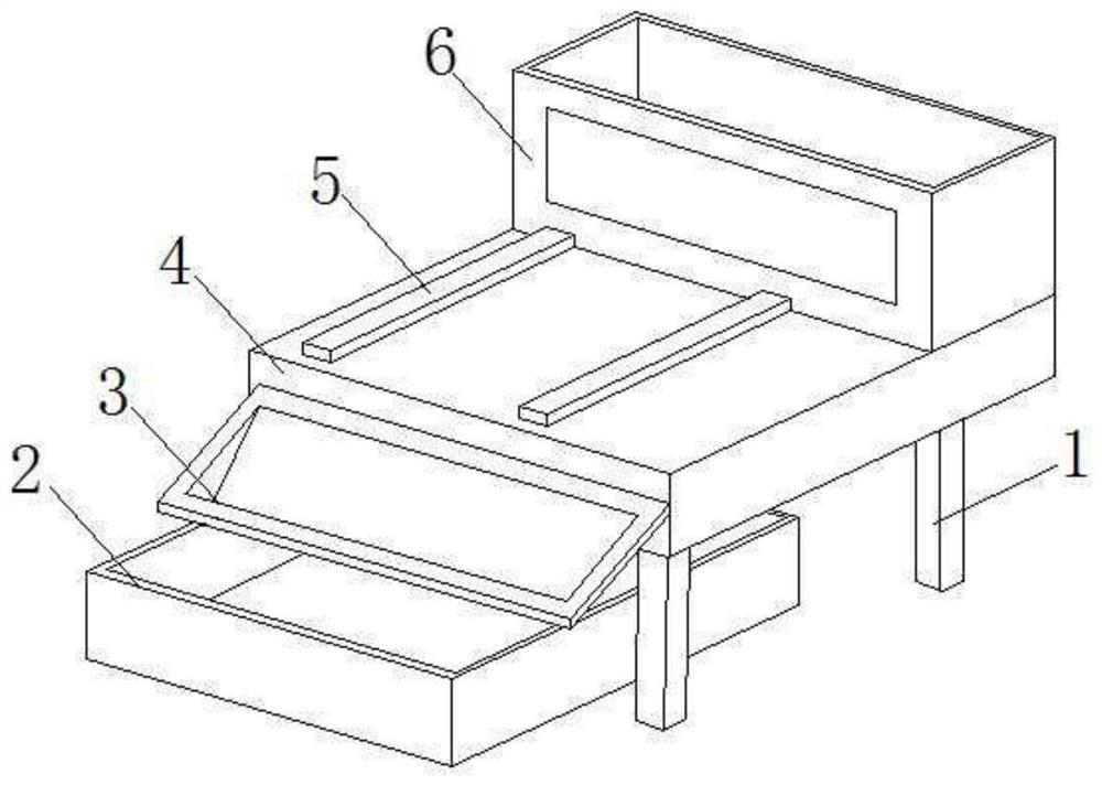
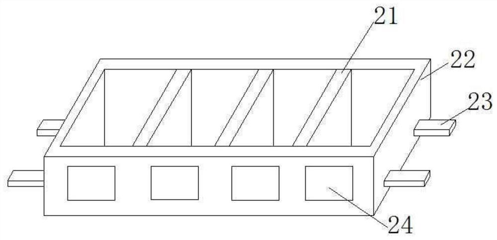
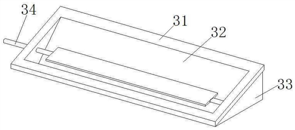
[0093]CombineFigure 1 to Figure 13The mechanical processing waste material collection device of the present invention will be described in detail.

[0094]The machined waste material collection device of this embodiment includes a leg 1. The leg 1 is rectangular parallelepiped. The frame 4 is rectangular parallelepiped. The frame 4 is fixed to the upper end of the leg 1 with bolts. The collection box 2 penetrates under the frame 4, and the collection box 2 slides along the length direction of the frame 4 under the frame 4. The guide frame 3 is pivotally connected to the end of the frame 4, and the guide frame 3 is placed above the collection box 2, and the lower edge of the guide frame 3 abuts against the upper end of the collection bo...


PUM


Abstract

The invention discloses a machining waste material collecting device, the device comprises supporting legs and further comprises a machine frame which is in a cuboid shape and is fixed to the upper ends of the supporting legs, a collecting box is arranged below the machine frame in a penetrating manner, a guide frame is pivoted to the end part of the machine frame and is placed above the collecting box, first guide rails are fixed to the top end of the machine frame in the length direction of the machine frame, the two first guide rails are arranged in parallel, a material box is supported atthe upper end of the machine frame and slides along the first guide rails, a guide frame comprises a rectangular frame, a supporting block is triangular and is fixed on the lower side of the end partof the frame, a conveying frame is pivoted in an inner cavity of the frame, a shifting piece is pivoted in the frame in the axial direction of the frame, a material box comprises a shell which is in acuboid shape, a discharge window is rectangular and is pivoted to the side wall of one side of the shell, a material removing piece is fixed on the side wall of the other side of the shell, and therefore, the machining waste material collecting device can collect waste materials and meanwhile has good self-buffering protection capacity.

Description

Technical field[0001]The invention relates to the technical field of mechanical equipment, in particular to a collection device for machining waste materials.Background technique[0002]Waste materials will be generated during the machining process. The waste materials need to be collected in time to avoid affecting the subsequent machining procedures. The accumulation of a large amount of waste materials will cause environmental pollution. When the existing waste material collection equipment collects waste materials, the waste materials directly scratch and hit the surface of the equipment. Since many of the waste materials are metal materials, their own materials are relatively hard and heavy, and they are likely to cause damage to the equipment itself after hitting the equipment. The existing waste material collection device itself lacks necessary buffer protection measures, so that it is easy to cause its own damage while collecting waste materials.[0003]Therefore, there is a nee...

Claims


Application Information

Patent Timeline
Patent Type & Authority Applications(China)
IPC IPC(8): B23Q11/00
CPCB23Q11/0067
Inventor 胡夏妹朱佳徐天一
Owner 嘉兴沃瑞科技有限公司
Why Eureka
Try Eureka