New energy automobile charging pile capable of automatically taking up cables

A technology for new energy vehicles and charging piles, applied in electric vehicle charging technology, electric vehicles, charging stations, etc., can solve problems such as shortening the service life of cables, cables hanging on the ground, and abrasion of cable insulation layers. Longer service life, avoid damage, reduce the effect of rebound speed

Inactive Publication Date: 2021-02-19
广州碧愿贸易有限公司
View PDF0 Cites 5 Cited by
  • Summary
  • Abstract
  • Description
  • Claims
  • Application Information

AI Technical Summary

Problems solved by technology

[0003] The existing charging piles for new energy vehicles generally include a charging box, a charging cable, and a charging gun. When charging, you need to remove the charging gun and insert it into the charging port of the car. During the process, it is easy for the cable to hang on the ground, which will not only cause the cable to be contaminated with dust, but also increase the wear of the cable insulation layer, and when the charging is completed, the charging gun and cable need to be retracted manually, which not only increases the The amount of labor is increased, making the charging process cumbersome, and the cable cannot be automatically recovered and exposed to the outside, which will shorten the service life of the cable over time
In addition, some charging pil

Method used


Image

  • New energy automobile charging pile capable of automatically taking up cables
  • New energy automobile charging pile capable of automatically taking up cables
  • New energy automobile charging pile capable of automatically taking up cables

Examples


Embodiment Construction

[0025] The following will clearly and completely describe the technical solutions in the embodiments of the present invention with reference to the accompanying drawings in the embodiments of the present invention. Obviously, the described embodiments are only some, not all, embodiments of the present invention. Based on the embodiments of the present invention, all other embodiments obtained by persons of ordinary skill in the art without making creative efforts belong to the protection scope of the present invention.

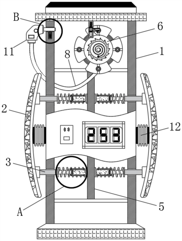
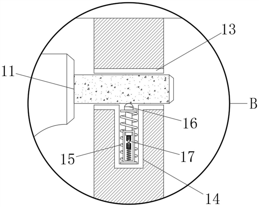
[0026] see Figure 1-5 , a new energy vehicle charging pile that can automatically take up the line, including a device main body 1, a card slot 13 is opened on the side wall of the device main body 1, a groove 14 is opened at the lower end of the card slot 13, and the bottom of the groove 14 is fixedly connected There is a second spring rod 15, the top of the second spring rod 15 is fixedly connected with a contact block 16, and the inside of the second sprin...


PUM


Abstract

The invention relates to the technical field of new energy, and discloses a new energy automobile charging pile capable of automatically taking up cables, which comprises an equipment main body; buffer pads are arranged on the two sides of the equipment main body; guide rods are fixedly connected to the ends, close to the equipment main body, of the buffer pads, and first spring rods are fixedly connected to the ends, away from the buffer pads, of the guide rods. According to the new energy automobile charging pile capable of automatically taking up wires, after charging is completed, a charging gun is placed in a clamping groove again; at the moment, the charging gun extrudes a contact block downwards, a switch assembly in a second spring rod abuts against the contact block, a circuit isclosed, an electromagnet is powered on, magnetism is enhanced, and a metal sliding block is attracted to slide upwards and abut against the electromagnet; a pawl synchronously moves along therewith and gradually gets away from a ratchet wheel, a coil spring gradually resets and drives the ratchet wheel to rotate anticlockwise, the ratchet wheel drives a winding roller to rotate synchronously, thewinding roller winds a cable, and the cable is prevented from being excessively exposed outside and being contaminated and damaged.

Description

technical field [0001] The invention relates to the field of new energy technologies, in particular to a charging pile for new energy vehicles that can automatically take up wires. Background technique [0002] New energy vehicles refer to new vehicles that use unconventional vehicle fuels as power sources, including gasoline-electric hybrid vehicles, solar vehicles, and the most common pure electric vehicles. Among them, pure electric vehicles are powered by on-board power supplies, so charging piles are needed to supplement their energy. [0003] The existing charging piles for new energy vehicles generally include a charging box, a charging cable, and a charging gun. When charging, you need to remove the charging gun and insert it into the charging port of the car. During the process, it is easy for the cable to hang on the ground, which will not only cause the cable to be contaminated with dust, but also increase the wear of the cable insulation layer, and when the char...

Claims


Application Information

Patent Timeline
IPC IPC(8): B60L53/31B60L53/16B65H75/48H02G11/02F16F15/023F16F15/067
CPCB65H75/48B60L53/16B60L53/31F16F15/023F16F15/067H02G11/02Y02T10/70Y02T10/7072Y02T90/12Y02T90/14
Inventor 何良荣
Owner 广州碧愿贸易有限公司
Why Eureka
Try Eureka