Building construction safety elevator

A technology for building construction and elevators, applied in elevators, elevators in buildings, mechanical equipment, etc., can solve the problems of high use frequency of elevators, affecting the use of elevator boxes, broken teeth of gears, etc., and achieve the effect of reducing impact force.

Inactive Publication Date: 2021-02-19
邢明款
View PDF8 Cites 0 Cited by
  • Summary
  • Abstract
  • Description
  • Claims
  • Application Information

AI Technical Summary

Problems solved by technology

[0003] However, due to the high frequency of use of the lift and the heavy load of the lift box, in order to increase the power input of the lift box, the gears are small in size, which is prone to broken teeth, which directly affects the use of the lift box. In the case of continuous broken teeth, it is easy to cause a major box drop accident; and the moment when the lifting box starts to rise or descends to stop, an impact load will be generated due to the action of inertial force, which will greatly reduce the service life of the motor-driven reducer components.

Method used


Image

  • Building construction safety elevator
  • Building construction safety elevator
  • Building construction safety elevator

Examples


Embodiment 1

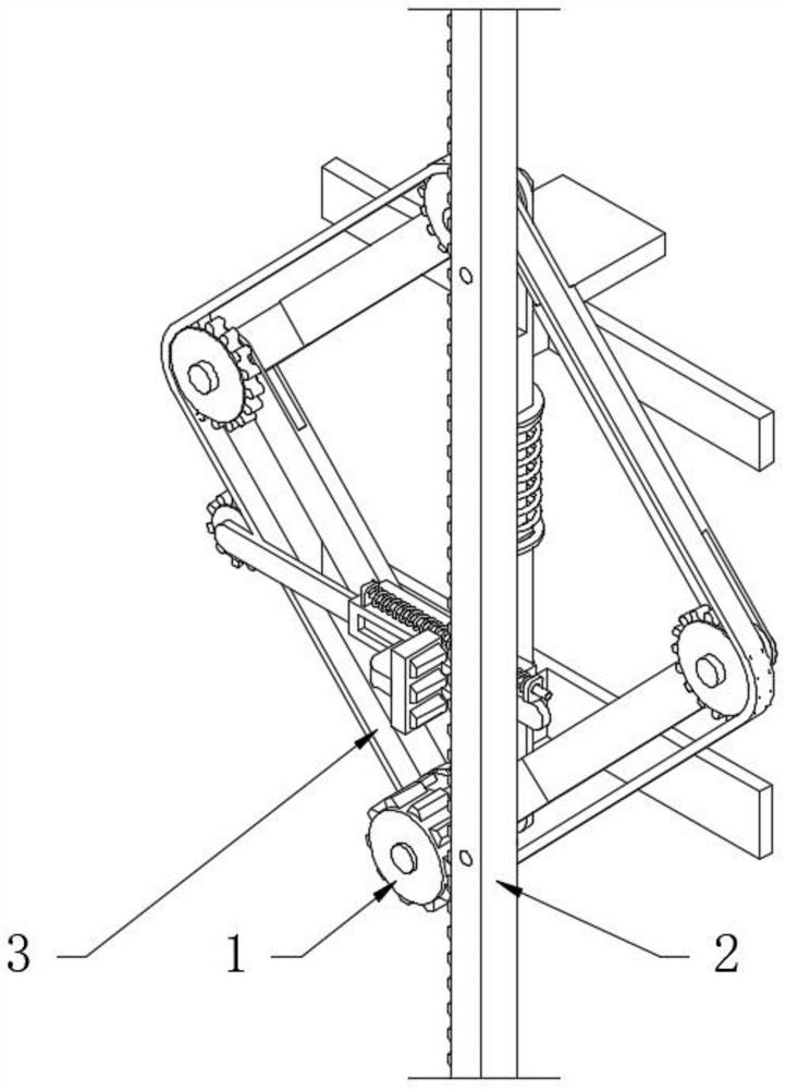
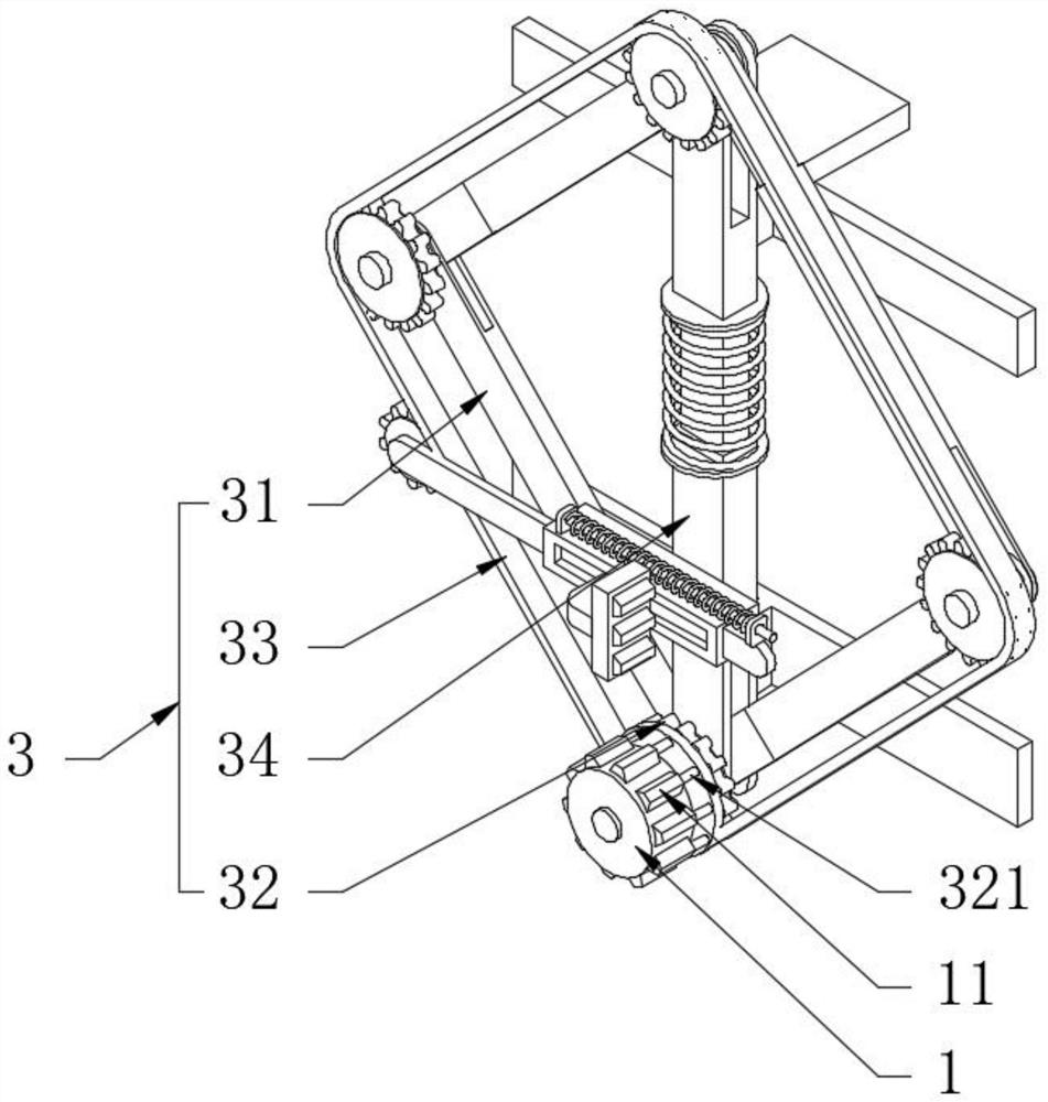
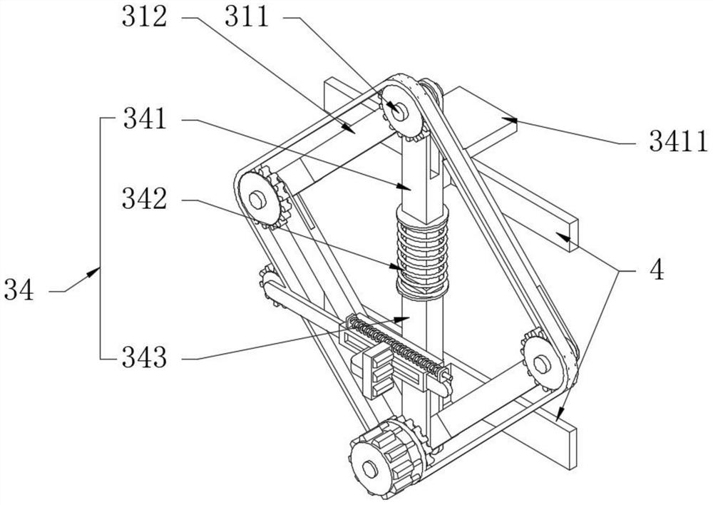
[0030] see Figure 1-3 , a building construction safety elevator, including a gear 1 and a rack 2 meshed with the gear 1. This embodiment is created on the basis of the existing gear 1 and the rack 2 meshing to realize lifting; it also includes a driving buffer chain Combination 3, the drive buffer chain combination 3 is the inventive structure of this embodiment, which can effectively solve the problem of broken teeth of the gear 1 and prolong the service life of the gear 1, and can also reduce the impact load of the drive input mechanism; the details are as follows The drive buffer chain combination 3 comprises a parallel hinge four-bar mechanism 31, a main sprocket wheel 32, a chain 33 and a spring damping rod 34, and the parallel hinge four-bar mechanism 31 is composed of four connecting rods with the same length. Rod 34 is positioned at parallel hinge four-bar mechanism 31 and is vertical distribution, and the two ends of this spring damping lever 34 are correspondingly c...

Embodiment 2

[0032] see Figure 4The difference from Embodiment 1 is that an elastic anti-drop condensation mechanism 5 is provided on the side of the lower sleeve 343 close to the rack 2, one end of the elastic anti-fall condensation mechanism 5 is engaged with the chain 33 and the other end is used in conjunction with the rack 2, The effect of this elastic anti-fall condensation mechanism 5 is that after the chain 33 in the embodiment 1 is accidentally disconnected, one end of the elastic anti-fall condensation mechanism 5 is instantly engaged with the rack 2. At this time, the lower casing 343 is fixed relative to the rack 2, and then It has anti-fall effect; specifically, the elastic anti-fall condensation mechanism 5 includes a rectangular guide sleeve 51, a guide plate 52, a return spring 53, a locking plate 54 and a traction sprocket 55, and the guide plate 52 is set on the rectangular guide sleeve 51 throughout. The traction sprocket 55 is rotatably connected to one end of the guid...


PUM


Abstract

The invention discloses a building construction safety elevator. The building construction safety elevator comprises a gear and a rack matched with the gear in a meshed mode and further comprises a driving buffer chain combination, the driving buffer chain combination comprises a parallel hinge four-rod mechanism, main chain wheels, a chain and a spring damping rod, the spring damping rod is located in the parallel hinge four-rod mechanism and is vertically distributed, and the two ends of the spring damping rod are correspondingly and rotatably connected with two opposite hinge shafts on theparallel hinge four-rod mechanism. According to the building construction safety elevator, the parallel hinge four-rod mechanism is arranged, the main chain wheels are connected to the four hinge shafts of the parallel hinge four-rod mechanism, the chain is engaged with the four main chain wheels, the lowest main chain wheel is connected with the gear, specifically, a reinforcing shaft is arrangedon one side of the main chain wheel, one end of the reinforcing shaft is fixedly connected with one side of teeth on the gear, when lifting is conducted, loads borne by the teeth on the gear are mainly borne by the main chain wheels, and therefore the phenomenon of tooth breaking can be avoided.

Description

technical field [0001] The invention relates to the technical field of elevators for building construction, in particular to a safety elevator for building construction. Background technique [0002] The construction elevator, also known as the construction elevator for construction, is a construction machine often used in construction for carrying people and goods. The current elevator adopts rack and pinion transmission, and a steel structure derrick is built outside the building. The rack is fixed on the frame, and the elevator drives the reducer through the motor. Drive the gear to rotate, the gear and the rack mesh, and then passively realize the up and down movement of the lifting box. [0003] However, due to the high frequency of use of the lift and the heavy load of the lift box, in order to increase the power input of the lift box, the gears are small in size, which is prone to broken teeth, which directly affects the use of the lift box. In the case of continuous...

Claims


Application Information

Patent Timeline
Patent Type & Authority Applications(China)
IPC IPC(8): B66B11/02B66B5/28F16F15/067
CPCB66B5/282B66B11/0266F16F15/067
Inventor 邢明款
Owner 邢明款
Why Eureka
Try Eureka