Heat exchanger of air conditioner

A technology for air conditioners and heat exchangers, applied in heat exchange equipment, air conditioning systems, evaporators/condensers, etc., can solve the problems of inability to improve heat transfer efficiency and decline in electrical and thermal performance.

Inactive Publication Date: 2003-10-08
SAMSUNG ELECTRONICS CO LTD
View PDF0 Cites 0 Cited by
  • Summary
  • Abstract
  • Description
  • Claims
  • Application Information

AI Technical Summary

Problems solved by technology

[0007] However, in the conventional heat exchanger constructed as above, since a plurality of slits (5a, 5b, 5c, 5d, 5e, 5f) are formed on the flat fins 1, the flat fins 1 are replaced by The warm fluidization of the thermal fluid reduces the thickness of the boundary layer in particular and forms a thin temperature boundary layer respectively. Therefore, although the electrothermal performance is higher than that of the flat heat sink 1 without the slit shape, when comparing the local electrothermal performance, there is Such a disadvantage is that although a thin temperature boundary layer is formed on the upstream side slit portion (5a, 5b) of the flat heat sink 1 to improve the electrothermal performance, the downstream side slit portion (5c, 5d, 5e, 5f) , due to entering the temperature boundary layer formed in the above-mentioned upstream side slit portion (5a, 5b), the electrothermal performance is reduced, and a dead flow area 4 where the airflow does not flow is generated behind the electrothermal tube 2; The airflow between the sheets 1 flows in parallel without mixing, which also makes it impossible to improve the heat transfer efficiency by airflow mixing

Method used


Image

  • Heat exchanger of air conditioner
  • Heat exchanger of air conditioner
  • Heat exchanger of air conditioner

Examples


Embodiment Construction

[0022] An embodiment of the present invention will be described in detail below based on the drawings.

[0023] The structures in the drawings that are the same as the existing structures use the same names and symbols, and detailed descriptions thereof are omitted.

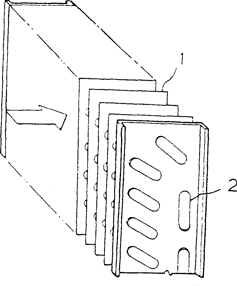
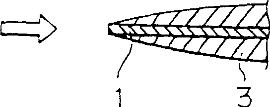
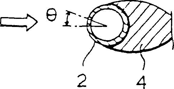
[0024] Figure 6 The reference number 20 in is a group of slit-type cutting fins. The group of slit-type cutting fins 20 are radially arranged on the flat plate heat sink 1 with respect to the upper and lower sides of the plurality of electric heating tubes 2 and the like, with the opening facing The upper and lower sides of the electric heating pipe 2 are surrounded by a certain base plate 21 in the direction of the air flow, so that the warm fluidization and mixing of the air flow flowing through the back and the surface of the plurality of flat fins 1 are reduced in the above-mentioned multiplication. The dead zone is generated at the rear of the electric heating tube 2, and the overall electric heating performan...


PUM


Abstract

A heat exchanger for an air conditioner having a plurality of parallel heat exchanging tubes passing through flat fins perpendicular thereto, the flat fins being arranged in parallel to each other at predetermined intervals, and each heat exchanging tube having fluids flowing inside therethrough, the heat exchanger comprising a plurality of louvers radially arranged around the tube, each louver being opened in flow direction of the air currents, such that the air currents flowing into the front and rear surfaces is turbulent around the tube, and first and second beads formed, respectively, before and behind the heat exchanging tubes in flow direction of the air currents, thereby enlarging a whole surface area of the flat fins, and reinforcing the flat fins, by which there is provided the turbulence and mixture of the air currents, further improving the heat transfer effect and reducing the air dead region around the heat exchanging tube. Also, the continuity of the heat transfer from the tube into other places can be guaranteed, with the improved heat transfer. Moreover, the beads provide the enlargement of the surface area of the flat fin and improved reinforcing thereof.

Description

Technical field [0001] The present invention relates to a heat exchanger for an air conditioner, in particular to an air conditioner in which a radial slit type (slittype) cutting fin group is formed on the upper and lower sides of an electric heating tube on a flat plate fin. The front and rear sides of the electric heating tube are formed with cut bends to warmly fluidize and mix the air flow (such as indoor air) passing through it, effectively reducing the dead water area behind the electric heating tube and improving heat transfer efficiency. Background technique [0002] Existing air conditioner heat exchangers such as figure 1 As shown, it is composed of a plurality of flat fins 1 and an electric heating tube 2. The plurality of flat fins 1 are arranged in parallel at a certain interval, and the electric heating tube 2 perpendicularly intersects the plurality of flat fins 1 and is arranged in a staggered shape. It is arranged so that the air flow flows in the direction of ...

Claims


Application Information

Patent Timeline
IPC IPC(8): F24F1/00F25B39/00F28F1/32F28F13/12
CPCY10S165/906F28F1/325Y10S165/503F28F1/32
Inventor 金永生
Owner SAMSUNG ELECTRONICS CO LTD
Why Eureka
Try Eureka