
Prefabricated steel-encased concrete column and concrete beam joint and construction process

A technology of reinforced concrete beams and concrete columns, which is applied in the direction of architecture and building construction, and can solve the problems of multiple construction procedures, heavy workload, and long construction period, and achieve the effects of simple construction procedures, improved earthquake resistance, and shortened construction period

Pending Publication Date: 2021-02-19
吉林建筑科技学院
View PDF0 Cites 0 Cited by
  • Summary
  • Abstract
  • Description
  • Claims
  • Application Information

AI Technical Summary

Problems solved by technology

[0002] At present, most of the building structures in my country are traditional cast-in-place concrete structures. The construction procedures of cast-in-place concrete structures are complicated, the construction period is long, and the seismic performance and ductility are poor. In the case of large-volume concrete or poor maintenance, it is easy to cause large-area structures Cracking and restricted by construction space, climate conditions, environmental protection and other factors
Practice has proved that the quality of column ductility and bearing capacity seriously affects the seismic performance of prefabricated frame structures, and there are disadvantages in prefabricated frame structures such as poor column bearing capacity and integrity, insufficient seismic capacity of nodes, and complicated construction procedures.
Moreover, in most prefabricated frame structures, the connection between beams and columns is mainly through the use of mechanical sleeves, welded connections or wet connections. indirect

Method used


Image

  • Prefabricated steel-encased concrete column and concrete beam joint and construction process
  • Prefabricated steel-encased concrete column and concrete beam joint and construction process
  • Prefabricated steel-encased concrete column and concrete beam joint and construction process

Examples


Embodiment 1

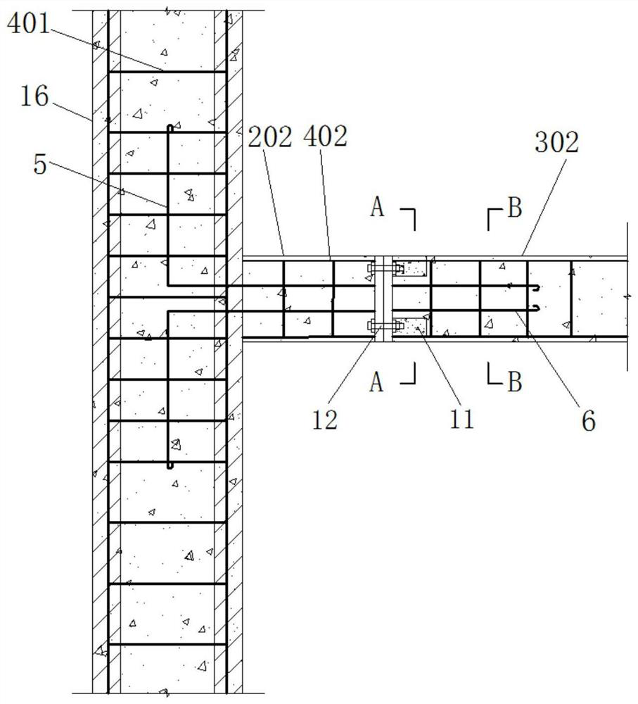
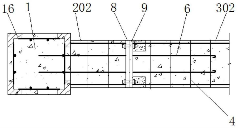
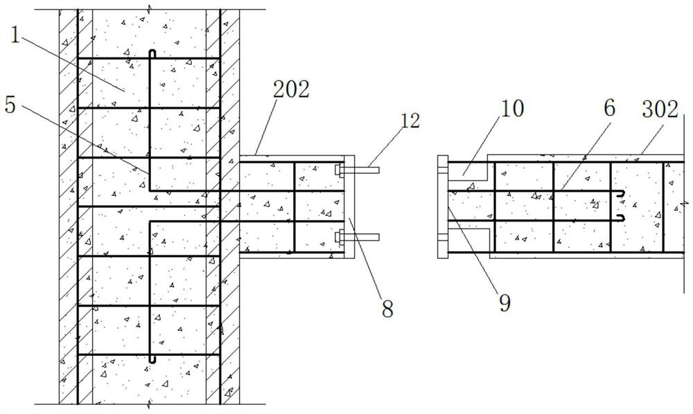
[0077] Such as Figure 1 to Figure 6As shown, the prefabricated outsourcing steel concrete column and the concrete beam joint include the prefabricated outsourcing steel concrete column 1, the prefabricated reinforced concrete beam 202 and the prefabricated reinforced concrete beam 302 embedded on the column; the prefabricated outsourcing steel concrete column 1 Including the steel skeleton 4 in the column, the outsourcing angle steel 16 and the anchoring steel bar 5 in the column, the outsourcing angle steel 16 is evenly distributed along the circumferential direction, and the steel skeleton 4 in the column is arranged at the geometric center of the area surrounded by the outsourcing angle steel 16, and the support of the outsourcing angle steel 16 The inner surface of the arm is welded to the end of the stirrup 401 of the steel skeleton 4 in the column, and the anchor steel bar 5 in the column is arranged inside the steel skeleton 4 in the column, and the two ends of the anch...

Embodiment 2

[0086] Such as Figure 7 to Figure 10 As shown, the difference between embodiment 2 and embodiment 1 is that the sections of the prefabricated reinforced concrete beam 202 and the prefabricated reinforced concrete beam 302 embedded on the column are both T-shaped, and the end plate I8 and the end plate II9 are both T-shaped end plate.

Embodiment 3

[0088] Such as Figure 11 to Figure 15 As shown, the difference between embodiment 3 and embodiment 1 is that the lower surfaces of the prefabricated reinforced concrete beams 202 and 302 prefabricated on the columns are respectively provided with outsourcing steel bottom plates 7, and one of the outsourcing steel The end of the base plate 7 is welded to the end plate I8, the end of the other outsourcing steel base plate 7 is welded to the end plate II9, and the upper surface of the outsourcing steel base plate 7 is welded to the stirrup 401 of the beam inner steel skeleton 4.

[0089] The construction technology of prefabricated steel-clad concrete columns and concrete beam joints includes the following steps:

[0090] Step 1, component making:

[0091] Manufacture a member composed of prefabricated steel-clad concrete column 1 and prefabricated reinforced concrete beam 202 pre-buried on the column, arrange the anchor steel bars 5 in the column according to the design, bind ...


PUM


Abstract

The invention discloses a prefabricated steel-encased concrete column and concrete beam joint and a construction process. The prefabricated steel-encased concrete column and concrete beam joint is divided into three forms, the first form is composed of a prefabricated steel-encased concrete column, a prefabricated reinforced concrete beam pre-buried in the column and a prefabricated reinforced concrete beam; the second form is composed of a prefabricated steel-encased concrete column, a prefabricated steel-encased concrete beam pre-buried in the column and a prefabricated steel-encased concrete beam; the third form is composed of a prefabricated steel-encased concrete column and a prefabricated reinforced concrete beam; and in order to overcome the defect of insufficient bearing capacity of a fabricated frame structure column, the steel-encased concrete column is adopted to replace a common reinforced concrete column. According to the steel-encased structure, loads of components and the structure are basically not increased, an originally designed structure system and a stress form are not changed, on one hand, the steel-encased reinforcement supplements the defects of steel bars of the original components and effectively improves the bearing capacity of the original components, on the other hand, through large-area steel plate adhesion, concrete of the original components is effectively protected, crack development is limited, and the rigidity and the crack resistance of the original components are improved.

Description

technical field [0001] The invention belongs to the technical field of building structures, and in particular relates to prefabricated steel-clad concrete columns and concrete beam joints and construction techniques. Background technique [0002] At present, most of the building structures in my country are traditional cast-in-place concrete structures. The construction procedures of cast-in-place concrete structures are complicated, the construction period is long, and the seismic performance and ductility are poor. In the case of large-volume concrete or poor maintenance, it is easy to cause large-area structures Cracking is restricted by factors such as construction space, climatic conditions, and environmental protection. Practice has proved that the ductility and bearing capacity of the columns seriously affect the seismic performance of the prefabricated frame structure, and there are disadvantages in the prefabricated frame structure such as poor column bearing capacit...

Claims


Application Information

Patent Timeline
Patent Type & Authority Applications(China)
IPC IPC(8): E04B1/58E04B1/30
CPCE04B1/185E04B1/30
Inventor 王连广周文君王蕾陈百玲杨丹萍张欧聂红鑫姚瑜
Owner 吉林建筑科技学院
Learn More