Method for reducing resistance of boiler smoke air duct system

A technology of flue gas duct and resistance, which is applied in the direction of combustion method, combustion product treatment, exhaust gas device, etc., and can solve the problem of low boiler operation efficiency

Pending Publication Date: 2021-02-19
HARBIN BOILER
View PDF11 Cites 2 Cited by
  • Summary
  • Abstract
  • Description
  • Claims
  • Application Information

AI Technical Summary

Problems solved by technology

[0003] The purpose of the present invention is to propose a method for reducing the resistance of the boiler flu...

Method used


Image

  • Method for reducing resistance of boiler smoke air duct system
  • Method for reducing resistance of boiler smoke air duct system
  • Method for reducing resistance of boiler smoke air duct system

Examples


specific Embodiment approach 1

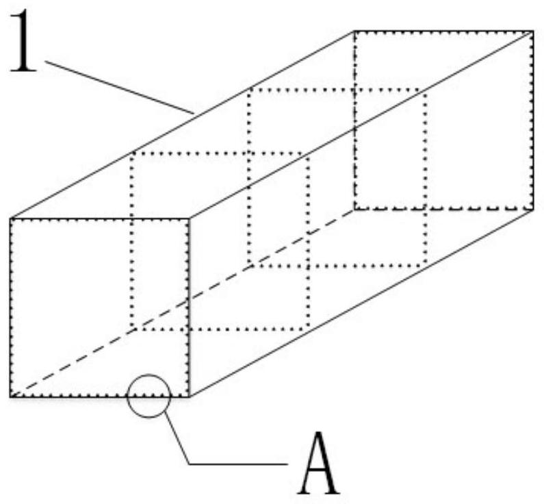
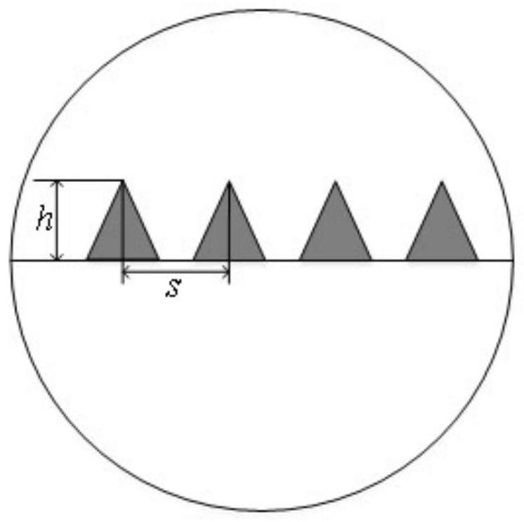
[0030] Specific implementation mode one: refer to figure 1 and figure 2 Specifically explaining this embodiment, a method for reducing the resistance of a boiler flue duct system described in this embodiment includes the following steps:

[0031] Step 1: Determine the height h of the V-shaped spoiler fins and the distance s between two adjacent V-shaped spoiler fins according to the thickness of the fluid turbulence boundary layer in the smoke duct;

[0032] Step 2: Obtain control parameters by controlling the ratio of dimensionless parameters, namely h / s, and combining CFD values;

[0033] Step 3: Arrange V-shaped spoiler fins in the flue gas duct according to the control parameters.

[0034] The specific idea of ​​this application is:

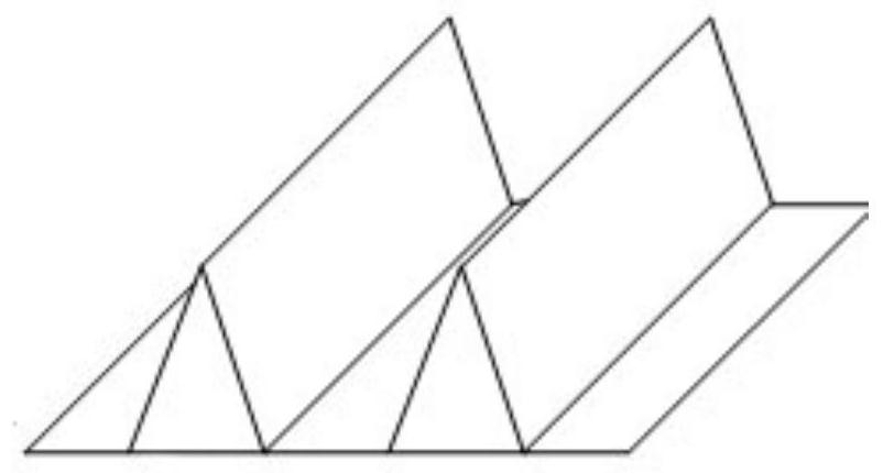
[0035] Arrange V-shaped spoiler fins in the smoke duct 1, such as image 3 As shown, the fluid flow in the flue gas duct is disturbed, so as to achieve the purpose of reducing the frictional resistance between the fluid and the inside of...

specific Embodiment approach 2

[0046] Embodiment 2: This embodiment is a further description of Embodiment 1. The difference between this embodiment and Embodiment 1 is that the step of obtaining the height h of the V-shaped spoiler fins in Step 1 is:

[0047] Firstly, the fluid flow velocity in the flue gas duct is obtained, and then the thickness of the turbulent boundary layer in the flue gas duct is obtained according to the fluid flow velocity in the flue gas duct, and the height h of the V-shaped spoiler fins is determined according to the thickness of the turbulent boundary layer in the flue gas duct.

specific Embodiment approach 3

[0048] Embodiment 3: This embodiment is a further description of Embodiment 2. The difference between this embodiment and Embodiment 2 is that the thickness of the turbulent boundary layer in the flue duct is obtained by calculating the turbulent boundary layer of a flat plate.


PUM


Abstract

The invention discloses a method for reducing resistance of a boiler smoke air duct system, and relates to the technical field of boiler air ducts. The method aims at solving the problem that in the prior art, the overall operation efficiency of a smoke air system boiler is low. The method comprises the following steps that firstly, a plurality of V-shaped turbulent flow fins are arranged in a smoke air duct; secondly, the height h of the V-shaped turbulent flow fins and the distance s between every two adjacent V-shaped turbulent flow fins are obtained; and thirdly, the ratio of dimensionlessparameters, namely h/s is controlled, control parameters are obtained in combination with CFD, and finally control over the resistance of the boiler smoke air duct system is completed according to the control parameters. The V-shaped fins are arranged in the smoke air duct, the friction resistance in a pipeline in the gas flowing process in the smoke air duct is reduced, and therefore the energyconsumption of the smoke air system is reduced, and the overall operation efficiency of a boiler is improved. According to the method, other variables are controlled to be unchanged, the value of h/sis changed, the optimal control value is found out, and the optimal drag reduction rate can reach 10.2%.

Description

technical field [0001] The invention relates to the technical field of boiler air ducts, in particular to a method for reducing the resistance of a boiler flue air duct system. Background technique [0002] The energy consumption of the flue gas system of the power station boiler accounts for about 30% of the power consumption of the plant, which seriously affects the overall operation economy of the boiler. Among them, the frictional resistance between the fluid flowing in the pipeline and the pipe wall is the main reason for increasing the energy consumption of the fan. At present, the measures taken by the power plant to reduce the energy consumption of the flue gas system mainly include: (1) install deflectors at the sharp turns of the flue gas duct; (2) install vane deflectors at the outlet of the dust collector; (3) Perform air plugging. The above methods can only be used to reduce the local resistance of the flue gas system, and there are still no effective measures ...

Claims


Application Information

Patent Timeline
IPC IPC(8): F23J13/08
CPCF23J13/08
Inventor 闫燕飞于强王静杰徐彦辉
Owner HARBIN BOILER
Why Eureka
Try Eureka