
Outer rotor permanent magnet motor and fan using same

A permanent magnet motor and external rotor technology, which is applied in the direction of machines/engines, electrical components, electromechanical devices, etc., can solve the problems that the angle of the extension rod cannot be adjusted, the center of gravity of the installation components is easy to shift, and the installation structure is unstable, so as to achieve small shaking , high installation stability and small runout tolerance

Inactive Publication Date: 2021-02-19
招国梅
View PDF11 Cites 1 Cited by
  • Summary
  • Abstract
  • Description
  • Claims
  • Application Information

AI Technical Summary

Problems solved by technology

[0004] In the above-mentioned patents, due to the large volume and high speed of the large outer rotor fan, it is easy to shake when rotating. Using the extension rod as a fixed structure will cause the installation structure of the fan to be unstable during operation, causing potential safety hazards. At the same time, the angle of the extension rod cannot be adjusted. The angle cannot be set when hanging on the mounting surface. In addition, the fan blades in the above-mentioned patents are fixedly installed on the outer rotor motor through the chassis and require additional mounting components. Fixed on the outer diameter of the outer rotor motor, the centrifugal force deviation will be infinitely magnified if the center of gravity shifts slightly during high-speed rotation, further affecting the stability of the fan

Method used


Image

  • Outer rotor permanent magnet motor and fan using same
  • Outer rotor permanent magnet motor and fan using same
  • Outer rotor permanent magnet motor and fan using same

Examples


Embodiment Construction

[0029] The following are specific embodiments of the present invention and in conjunction with the accompanying drawings, the technical solutions of the present invention are further described, but the present invention is not limited to these embodiments.

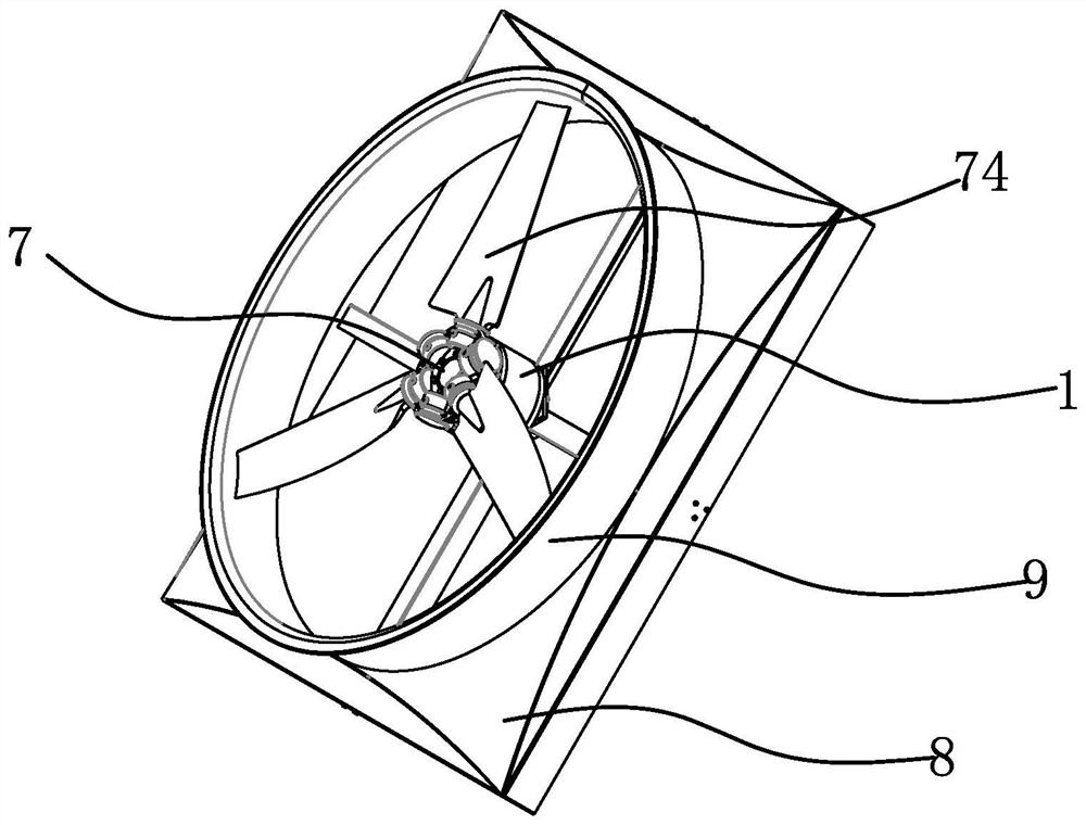
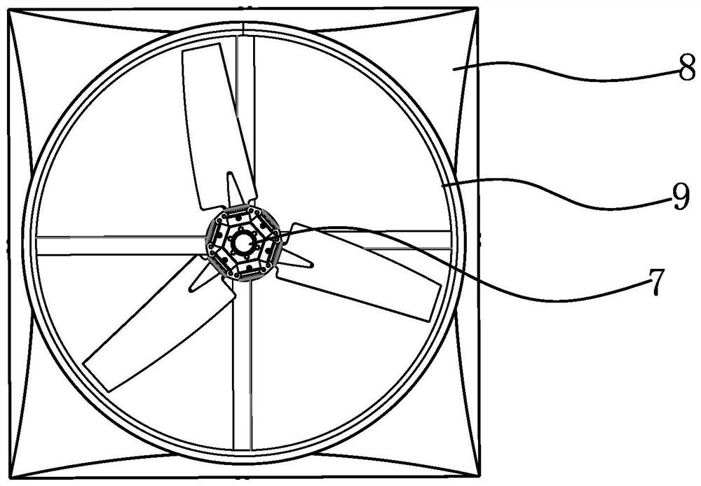
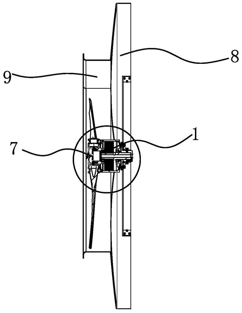
[0030] Such as Figure 1-4 As shown, the fan using the outer rotor permanent magnet motor includes an outer rotor permanent magnet motor. The outer rotor permanent magnet motor includes a fixed shaft 2 and a stator assembly 3 fixedly connected to the fixed shaft 2. The outside of the stator assembly 3 A rotor 4 is provided, and a front end cover 5 and a rear end cover 6 fixedly connected with the rotor 4 are arranged on both sides of the rotor 4, and a front end cover 5 and a rear end cover 6 are respectively arranged between the fixed shaft 2 and the The bearing 51 and the rear bearing 61 , the fixed shaft 2 protrudes from the rear end cover 6 , the front end cover 5 is provided with a load connection part 52 , and the fa...


PUM


Abstract

The invention provides an outer rotor permanent magnet motor and a fan using the same, and solves the problem of low structural stability of an outer rotor motor in the prior art. The motor comprisesa fixed shaft and a stator assembly fixedly connected with the fixed shaft, and a rotor is arranged on the outer side of the stator assembly. A front end cover and a rear end cover which are fixedly connected with the rotor are arranged on the two sides of the rotor, a front bearing and a rear bearing are arranged between the front end cover and the fixing shaft and between the rear end cover andthe fixing shaft respectively, the fixing shaft extends out of the rear end cover, a load connecting part is arranged on the front end cover, and the front end cover and the load connecting part are integrated. And the load connecting part is provided with a fan assembly. The installation stability of the fan is higher, the installation angle of the fan support can be set according to needs, and the operation stability is higher.

Description

technical field [0001] The invention belongs to the technical field of motors, and relates to an outer rotor permanent magnet motor and a fan using the motor. Background technique [0002] In factories, workshops, stations, airports and other places, large fans are often used for ventilation and heat dissipation; the existing large fans all use shaft output motors, which need to be installed and fixed through the bracket structure first, so that the volume of the fan Larger and heavier gravity, there are relatively high requirements for the installation structure load of the entire fan, which makes the installation difficult and the cost of the fan increases. [0003] Aiming at the above-mentioned problems existing in the prior art, those skilled in the art have made certain improvements, and designed an outer rotor fan in combination with the advantages of the outer rotor permanent magnet motor, such as a large outer rotor fan proposed by a Chinese patent (notification numb...

Claims


Application Information

Patent Timeline
Patent Type & Authority Applications(China)
IPC IPC(8): H02K5/16H02K5/124H02K7/14H02K11/30F04D25/06
CPCF04D25/062H02K5/124H02K5/161H02K7/14H02K11/30
Inventor 理查德·汉姆招国梅
Owner 招国梅
Learn More