Rebar shearing device with straightening structure

A shearing device and straightening technology, which is applied in the field of steel bar shearing, can solve the problems of steel bar toughness decline, unfavorable steel bar reuse, and high brittleness, and achieve the effects of increasing stress reduction, improving elimination effect, and improving straightening effect

Active Publication Date: 2022-06-28
铭际建筑科技(泰兴)有限公司
View PDF9 Cites 0 Cited by
  • Summary
  • Abstract
  • Description
  • Claims
  • Application Information

AI Technical Summary

Problems solved by technology

[0002] Steel bars are an indispensable basic material in the construction field. After use, steel bars may be deformed, which is not conducive to the reuse of steel bars after recycling.
[0003] The current steel bar straightening mainly uses the steel bar to pass through the high-speed rotating straightening roller, and the steel bar repeatedly rotates and bends in it, thereby eliminating the internal stress in it to achieve the purpose of straightening. However, the steel bar is driven to move during the rotation of the straightening roller. , and straighten the steel bar during the movement of the steel bar. This straightening method belongs to cold deformation. When the deformation of the steel bar is large, there will be a large deformation stress in the deformation area of ​​the steel bar, which will reduce the toughness of the steel bar and reduce the brittleness. becomes higher, making the steel bar very prone to breakage
[0004] Moreover, the straightening roller drives the steel bar to move and exerts pressure on the steel bar during the moving process, so that the bent part of the steel bar is compressed and straightened. The straightening process is a dynamic process. The inside of the straightened steel bar is deformed due to However, there is a certain stress, and the steel bar will be deformed again due to the slow release of the stress in the later use process.

Method used


Image

  • Rebar shearing device with straightening structure
  • Rebar shearing device with straightening structure
  • Rebar shearing device with straightening structure

Examples


Embodiment Construction

[0031] The technical solutions in the embodiments of the present invention will be clearly and completely described below with reference to the accompanying drawings in the embodiments of the present invention. Obviously, the described embodiments are only a part of the embodiments of the present invention, but not all of the embodiments. Based on the embodiments of the present invention, all other embodiments obtained by those of ordinary skill in the art without creative efforts shall fall within the protection scope of the present invention.

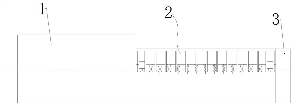
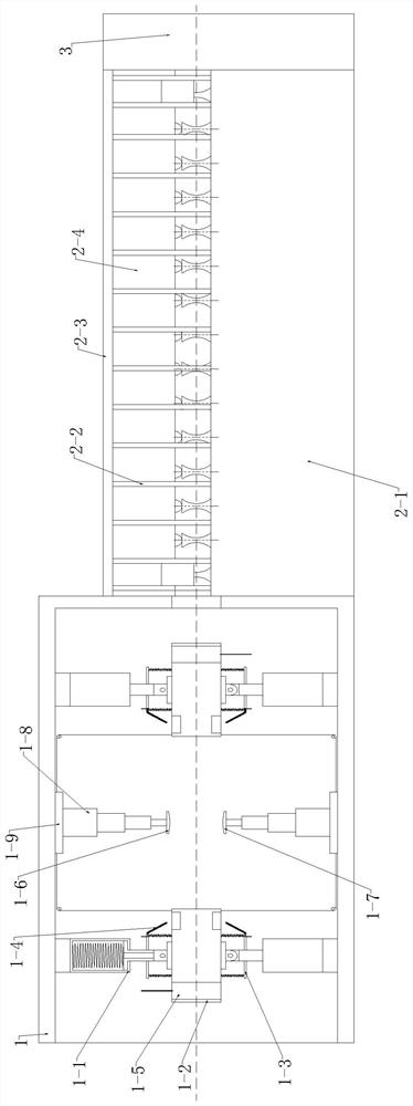
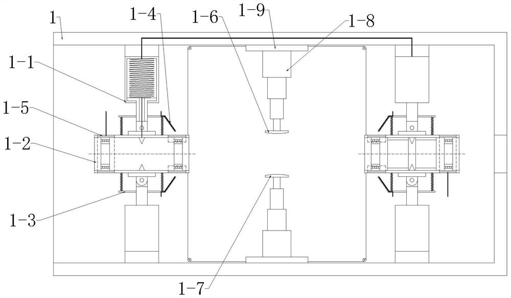
[0032] see Figure 1-8 , the present invention provides a technical solution: a steel bar shearing device with a straightening structure, the steel bar shearing device includes an electromagnetic tube 1, a straightening assembly 2, and a shearing assembly 3, the left end of the straightening assembly 2 is connected to the electromagnetic tube 1, and the straightening assembly 2. The right end is connected to the shearing component 3, ...


PUM


Abstract

The invention discloses a steel bar shearing device with a straightening structure. The steel bar shearing device includes an electromagnetic tube, a straightening assembly, and a shearing assembly. One end of the straightening assembly is connected to the electromagnetic tube, and the other end of the straightening assembly is connected to the shearing assembly. , the electromagnetic tube performs stress relief on the steel bar, and the straightening component performs straightening on the steel bar. The electromagnetic tube first makes the inner side of the bending part of the steel bar carry electrons through electrostatic induction, and then cuts the magnetic induction line of the steel bar to generate an induced current, heats the bending part of the steel bar, and then reduces the stress of the bending part, and finally through the eddy current effect. The overall heating can further reduce the existence of stress, improve the straightening effect of the straightening components on the steel bars, and prevent the steel bars from bending again under the action of stress after straightening.

Description

technical field [0001] The invention relates to the technical field of steel bar shearing, in particular to a steel bar shearing device with a straightening structure. Background technique [0002] Reinforcing steel is an indispensable basic material in the field of construction. After use, it may cause the deformation of the steel bar, which is not conducive to the reuse of the steel bar after recycling. [0003] The current steel bar straightening mainly uses the steel bar to pass through the high-speed rotating straightening roller, and the steel bar rotates and bends repeatedly in it, so as to eliminate the internal stress to achieve the purpose of straightening. , and straighten the steel bar during the movement of the steel bar. This straightening method belongs to cold deformation. When the deformation amount of the steel bar is large, there will be a large deformation stress in the deformation area of ​​the steel bar, which will reduce the toughness of the steel bar ...

Claims


Application Information

Patent Timeline
Patent Type & Authority Patents(China)
IPC IPC(8): B21F1/02B21F11/00B21F23/00
CPCB21F1/026B21F23/00
Inventor 吕彬鞠波陈敏朱鹏张红光
Owner 铭际建筑科技(泰兴)有限公司
Why Eureka
Try Eureka