Supercharge Your Innovation With Domain-Expert AI Agents!

Thrust plate, crankshaft assembly and engine

A thrust plate, crankshaft technology, applied in the directions of crankshaft bearings, shafts and bearings, bearing components, etc., can solve the problems such as the influence of bearing pads, poor cooling and lubrication, and main bearing pads.

Pending Publication Date: 2021-02-23
天津特瑞捷动力科技有限公司
View PDF0 Cites 0 Cited by
  • Summary
  • Abstract
  • Description
  • Claims
  • Application Information

AI Technical Summary

Problems solved by technology

When the thrust plate is assembled upside down, the oil passage groove of the thrust plate faces the main bearing housing, and the reserved oil passage with the rotating crank surface is missing, so that the oil film cannot be established between the thrust plate and the rotating crank surface
Cause poor cooling and lubrication, resulting in faults such as main bearing bushing
[0003] The current mainstream solutions, one is to control the problem of misassembly through on-site management and technological measures, and the other is to add a limit structure so that the thrust plate itself has directionality, and it cannot be assembled in the reverse direction.
Among them, process control can only reduce the probability of wrong installation, but cannot completely eliminate the occurrence of problems
Once there is a wrong installation, the bearing pad will have a great impact, and may even cause life safety; although adding a limit structure can prevent the wrong installation problem, it can only be found after the assembly error, and the problem must be found by manual assembly, and this method Unable to solve the problem of thrust plate wear

Method used


Image

  • Thrust plate, crankshaft assembly and engine

Examples


Embodiment Construction

[0018] In order to make the object, technical solution and advantages of the present invention clearer, the present invention will be further described in detail below in conjunction with specific embodiments and with reference to the accompanying drawings.

[0019] It should be understood, however, that these descriptions are exemplary only and are not intended to limit the scope of the present invention. In the following detailed description, for purposes of explanation, numerous specific details are set forth in order to provide a thorough understanding of the embodiments of the invention. It may be evident, however, that one or more embodiments may be practiced without these specific details. In addition, in the following description, descriptions of known technologies are omitted to avoid unnecessarily confusing the concept of the present invention.

[0020] The terminology used herein is for the purpose of describing particular embodiments only, and is not intended to b...


PUM

PropertyMeasurementUnit
Thicknessaaaaaaaaaa

Abstract

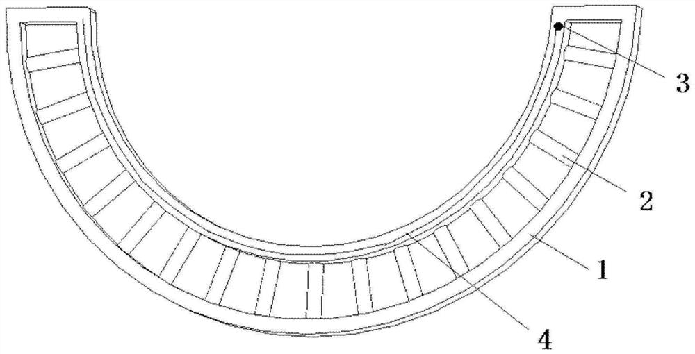
The invention discloses a thrust plate, a crankshaft assembly and an engine. The thrust plate comprises a thrust plate body, wherein an arc-shaped hollow groove is formed in the thrust plate body, andone or more rolling components are arranged in the hollow groove; and the rolling components are used for realizing rolling friction between the thrust plate and a crankshaft in the operation processof the crankshaft. The hollow groove is formed in the thrust plate body, and one or more rolling components are arranged in the hollow groove, so that the mode of friction between the thrust plate and the crankshaft is improved from sliding friction to rolling friction, the wear rate of the thrust plate is greatly reduced, and the service life is prolonged.

Description

technical field [0001] The invention relates to the technical field of engines, in particular to a thrust plate, a crankshaft assembly and an engine. Background technique [0002] In the engine manufacturing industry, especially the assembly of engine internal parts will directly affect the performance and quality of the whole machine. When assembling the thrust plate of the crankshaft thrust gear, the direction of the thrust plate is easy to be assembled in the opposite direction. When the thrust plate is assembled upside down, the oil passage groove of the thrust plate faces the main bearing housing, and the reserved oil passage with the rotating crank surface is missing, so that the oil film cannot be established between the thrust plate and the rotating crank surface. Causes poor cooling and lubrication, which leads to failures such as main bearing bushing. [0003] The current mainstream solutions, one is to control the problem of misassembly through on-site managemen...

Claims


Application Information

Patent Timeline
IPC IPC(8): F16C9/02F16C33/66
CPCF16C9/02F16C33/6659F16C33/6681
Inventor 豆刚周涛郭晓轩
Owner 天津特瑞捷动力科技有限公司
Features
  • R&D
  • Intellectual Property
  • Life Sciences
  • Materials
  • Tech Scout
  • Unparalleled Data Quality
  • Higher Quality Content
  • 60% Fewer Hallucinations
Learn More