
Multi-stage isolation lampblack purification device

A lampblack purification and separation device technology, applied in the field of lampblack purification, can solve the problems of affecting the service life of equipment, difficult to clean up oil dirt, difficult to clean, etc., to achieve the effect of improving the effect of fume purification, facilitating later cleaning, and improving service life

Pending Publication Date: 2021-02-23
ANQING SANWEI ELECTRICAL
View PDF1 Cites 1 Cited by
  • Summary
  • Abstract
  • Description
  • Claims
  • Application Information

AI Technical Summary

Problems solved by technology

The emission of oily fume from catering has always been a key and difficult point in the control of kitchen environment and air pollution sources, especially in hotels, institutions, schools, factories and other places. The air duct takes up a lot of space, and the oil in the air duct is not easy to clean. The oil is easy to seep out from the joints or gaps of the air duct, causing secondary pollution, which is not conducive to long-term use
[0003] At present, there is a single treatment method for oil fume purification. For example, the Chinese Invention Patent Publication No. CN106196214A discloses a cooking oil fume condensation purifier, which uses a condensation process to purify the oil fume, but the oil fume condenses and adheres to the surface of the range hood equipment, which is difficult to clean and will corrode the equipment for a long time , affects the service life of the equipment, and the method of purifying the oil fume only through physical processes is not thorough. The black smoke particles and chemical gel in the oil fume will still pollute the environment, and the oil fume purification effect is poor

Method used


Image

  • Multi-stage isolation lampblack purification device
  • Multi-stage isolation lampblack purification device
  • Multi-stage isolation lampblack purification device

Examples


Embodiment Construction

[0029] In order to facilitate those skilled in the art to understand the technical solution of the present invention, the technical solution of the present invention will be further described in conjunction with the accompanying drawings.

[0030] In this application, terms such as "installation", "connection", "connection" and "fixation" should be interpreted in a broad sense, for example, it can be a fixed connection or a detachable connection, unless otherwise clearly specified and limited. , or integrated; it can be a mechanical connection, an electrical connection, or a communication; it can be a direct connection or an indirect connection through an intermediary, it can be the internal communication of two components or the interaction relationship between two components . Those of ordinary skill in the art can understand the specific meanings of the above terms in this application according to specific situations.

[0031] The terms "first" and "second" are used for de...


PUM


Abstract

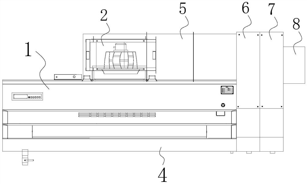
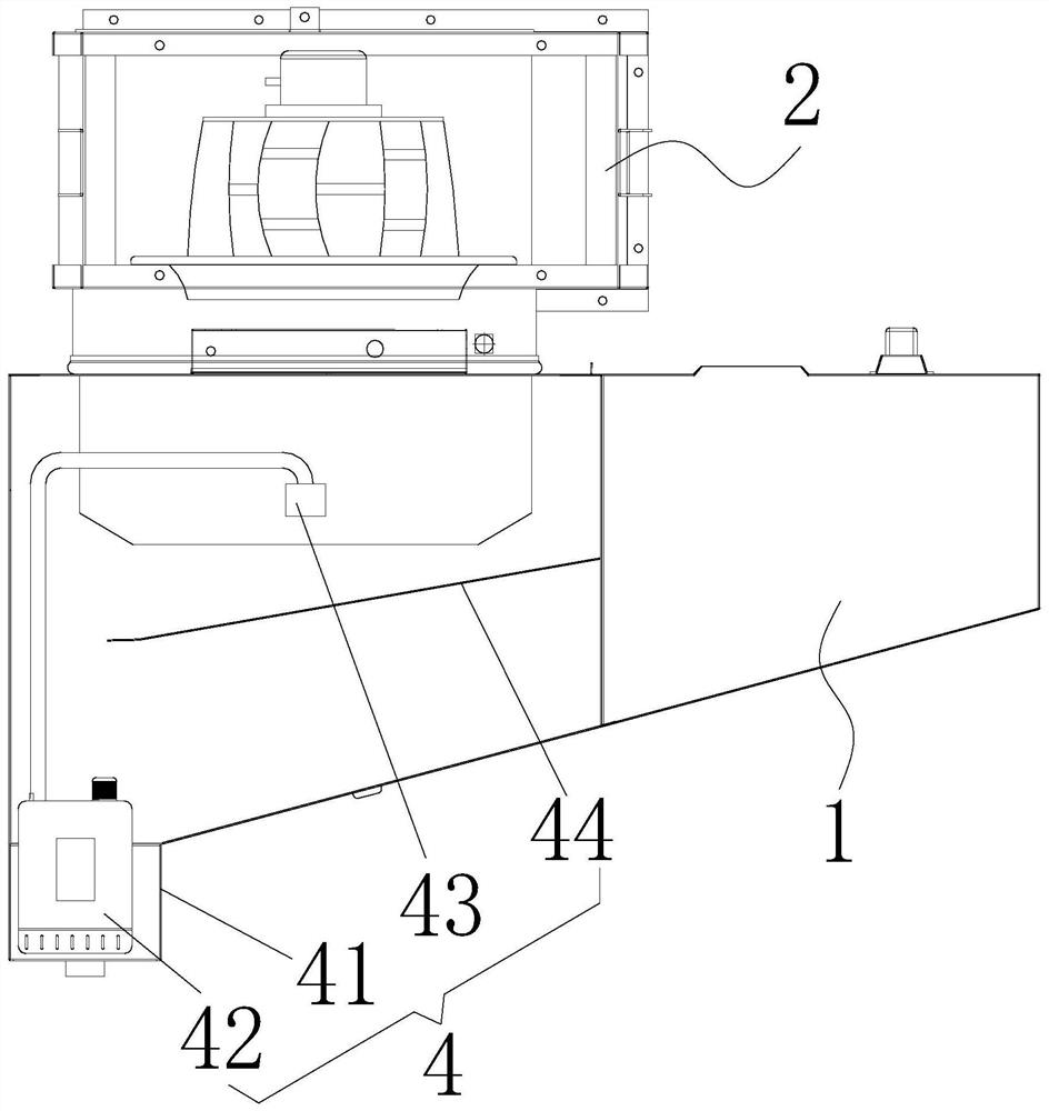
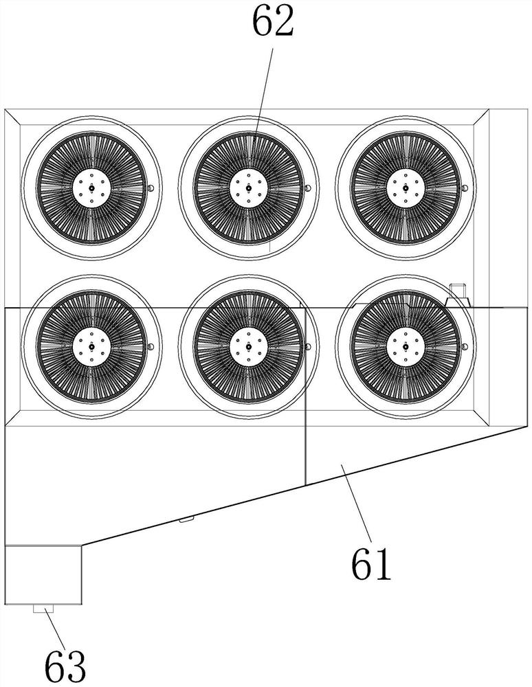
The invention discloses a multi-stage isolation lampblack purification device which comprises a lampblack collection cabinet body, a negative pressure fan, a first-stage separation device, a second-stage separation device, a third-stage separation device, a fourth-stage separation device and a lampblack exhaust pipe. The negative pressure fan is fixed to the lampblack collection cabinet body, andthe first-stage separation device and the second-stage separation device are fixed to a gas inlet of the lampblack collection cabinet body; and an air outlet of the negative pressure fan is sequentially communicated with the third-stage separation device and the fourth-stage separation device and is communicated with the lampblack exhaust pipe. The multi-stage isolation lampblack purification device has the advantages that according to the multi-stage isolation lampblack purification device, through the arrangement of the first-stage separation device, the second-stage separation device, the third-stage separation device and the fourth-stage separation device, four-stage filtration and separation of lampblack are achieved, the lampblack purification effect is improved, the lampblack reaches the emission standard, the lampblack can be prevented from being condensed and attached to the surface of range hood equipment, later-stage cleaning is facilitated, and the service life of the device is prolonged.

Description

technical field [0001] The invention relates to the technical field of oil fume purification, in particular to a multi-stage isolated oil fume purification device. Background technique [0002] Drinking fume exhaust gas is a volatile substance produced by a series of complex chemical reactions such as thermal oxidation and thermal cracking of edible oil and food at high temperature. The composition is relatively complex, mainly including aldehydes, ketones, hydrocarbons, fatty acids, and aromatic compounds. And heterocyclic compounds, which have three forms: gaseous, liquid small particles and solid small particles. The emission of oily fume from catering has always been a key and difficult point in the control of kitchen environment and air pollution sources, especially in hotels, institutions, schools, factories and other places. The air duct takes up a lot of space, and the oil in the air duct is not easy to clean. The oil is easy to seep out from the joints or gaps of t...

Claims


Application Information

Patent Timeline
Patent Type & Authority Applications(China)
IPC IPC(8): F24C15/20F24C15/00B01D50/00B01D53/74B01D53/76
CPCF24C15/20F24C15/2057F24C15/2035F24C15/00B01D53/007B01D53/74B01D53/76B01D2251/104B01D2259/804B01D50/10
Inventor 程新沈三九张旱生张宇王欢蒋玉和
Owner ANQING SANWEI ELECTRICAL
Learn More