
Current measuring device

A current measurement device and magnetic field measurement technology, applied in the direction of using digital measurement technology for measurement, etc., can solve the problems of low applicability, iron loss, large power consumption, etc.

Pending Publication Date: 2021-02-23
CHINA SOUTHERN POWER GRID DIGITAL GRID RES INST CO LTD +3
View PDF9 Cites 1 Cited by
  • Summary
  • Abstract
  • Description
  • Claims
  • Application Information

AI Technical Summary

Problems solved by technology

The measurement accuracy of the electromagnetic current transformer can reach a few thousandths, but due to the influence of the iron core, there are iron losses and large power consumption
The measurement method of the Rogowski coil requires that the measured wire should be in the center of the coil to ensure that the magnetic field at each part of the ring is equal, and there are certain requirements for the shape of the measured wire, which has low applicability.

Method used


Image

  • Current measuring device
  • Current measuring device
  • Current measuring device

Examples


Embodiment Construction

[0021] In order to facilitate the understanding of the present application, the present application will be described more fully below with reference to the relevant drawings. Embodiments of the application are given in the drawings. However, the present application can be embodied in many different forms and is not limited to the embodiments described herein. On the contrary, the purpose of providing these embodiments is to make the disclosure of this application more thorough and comprehensive.

[0022] Unless otherwise defined, all technical and scientific terms used herein have the same meaning as commonly understood by one of ordinary skill in the technical field to which this application belongs. The terms used herein in the specification of the application are only for the purpose of describing specific embodiments, and are not intended to limit the application.

[0023] It can be understood that the terms "first", "second" and the like used in this application may be...


PUM


Abstract

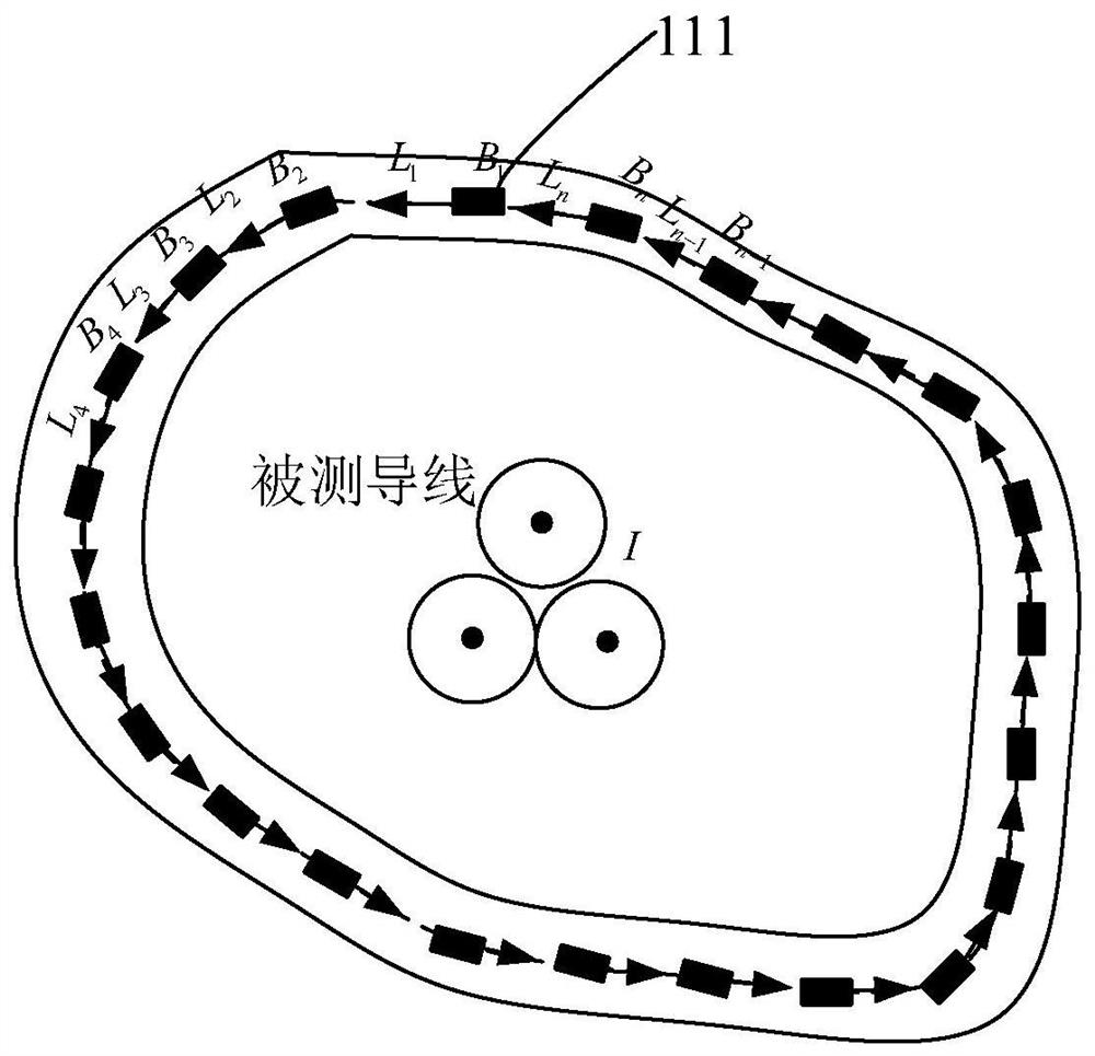
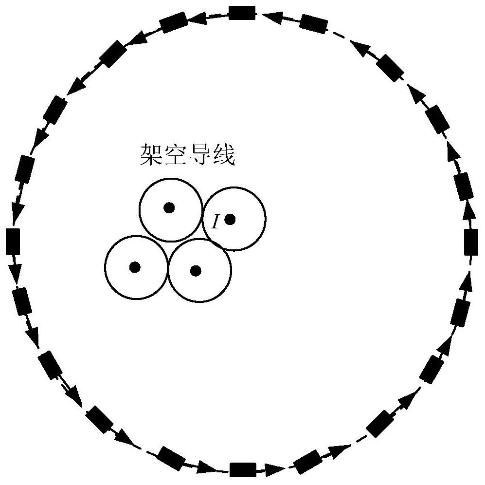
The invention relates to a current measuring device, which comprises a sensing circuit, an addition circuit and a processing unit. The sensing circuit comprises a plurality of magnetic field measuringchips which are arranged at intervals to form a closed pattern, each magnetic field measuring chip is connected with the input end of the addition circuit, the output end of the addition circuit is connected with the processing unit, and a measured wire passes through a plane where the closed pattern enclosed by the plurality of magnetic field measuring chips is located. The magnetic field measuring chips sense a current passing through the measured wire and output induction voltages to the addition circuit, the addition circuit adds the induction voltages output by the magnetic field measuring chips and then outputs the total voltage to the processing unit, and the processing unit obtains the current value of the measured wire according to the total voltage. By the adoption of the device, the defect that the measured wire needs to be located in the center can be effectively overcome, the applicability is high, iron loss caused by an iron core can be avoided, and the power consumptionis reduced.

Description

technical field [0001] The present application relates to the technical field of power instrument testing, in particular to a current measuring device. Background technique [0002] With the increase of the transmission capacity of the power system, the improvement of the voltage level, and the introduction of the smart grid concept and its continuous maturity in recent years, higher requirements have been placed on the equipment for the collection and detection of power grid signals, especially for the acquisition There are new expectations for the accuracy, stability, and rapidity of grid signals. Therefore, the equipment for measuring current is the most important link between the grid signal and the computer system. For example, the accuracy and real-time performance of the current transformer signal acquisition will affect the accurate analysis of the fault by the computer system. [0003] Traditionally, electromagnetic current transformers or Rogowski coils are genera...

Claims


Application Information

Patent Timeline
IPC IPC(8): G01R19/25
CPCG01R19/25
Inventor 李鹏张佳明尹旭钟连宏余文辉周柯徐长宝赵继光田兵王志明辛明勇王晓明
Owner CHINA SOUTHERN POWER GRID DIGITAL GRID RES INST CO LTD
Learn More