
Display panel and electronic device

A display panel and panel technology, applied in the direction of circuits, electrical components, electric solid devices, etc., can solve the problems of falling off under force, poor position accuracy of UV coating, uneven thickness, etc.

Pending Publication Date: 2021-02-23
WUHAN CHINA STAR OPTOELECTRONICS SEMICON DISPLAY TECH CO LTD
View PDF0 Cites 1 Cited by
  • Summary
  • Abstract
  • Description
  • Claims
  • Application Information

AI Technical Summary

Problems solved by technology

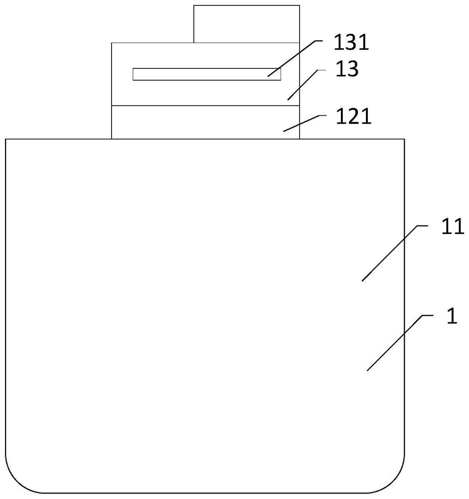
[0003] During the research and practice of the prior art, the inventors of the embodiments of the present invention found that in order to enhance the protection performance at the source and drain metal traces in the bending area, please refer to figure 1 , in the prior art, only the bending part is set in the bending area. In order to prevent the bending area from breaking during bending, UV curing (Ultraviolet, UV) glue is generally applied on the bending area, which helps to reduce the Tensile stress, but the accuracy of UV coating position is poor, the coating boundary is not well controlled, and the thickness of different areas is uneven, the viscosity is poor, and the force may fall off. At the same time, UV glue can only be used for partial protection. In the process of testing, testing, mobile phone assembly, etc., the source and drain metal wires on both sides are under the greatest force, and are easily subject to external force collisions, interference and other factors, which may cause the source and drain metal wires on both sides to break, thereby damaging the flexible display screen, resulting in Lower product yield

Method used


Image

  • Display panel and electronic device
  • Display panel and electronic device
  • Display panel and electronic device

Examples


Embodiment Construction

[0026] The technical solutions in the embodiments of the present application will be clearly and completely described below in conjunction with the drawings in the embodiments of the present application. Apparently, the described embodiments are only some of the embodiments of this application, not all of them. Based on the embodiments in this application, all other embodiments obtained by those skilled in the art without making creative efforts belong to the scope of protection of this application.

[0027] In the description of the present application, it should be understood that the terms "first" and "second" are used for description purposes only, and cannot be interpreted as indicating or implying relative importance or implicitly indicating the quantity of indicated technical features. Thus, features defined as "first" and "second" may explicitly or implicitly include one or more of said features. In the description of the present application, "" means two or more, unl...


PUM


Abstract

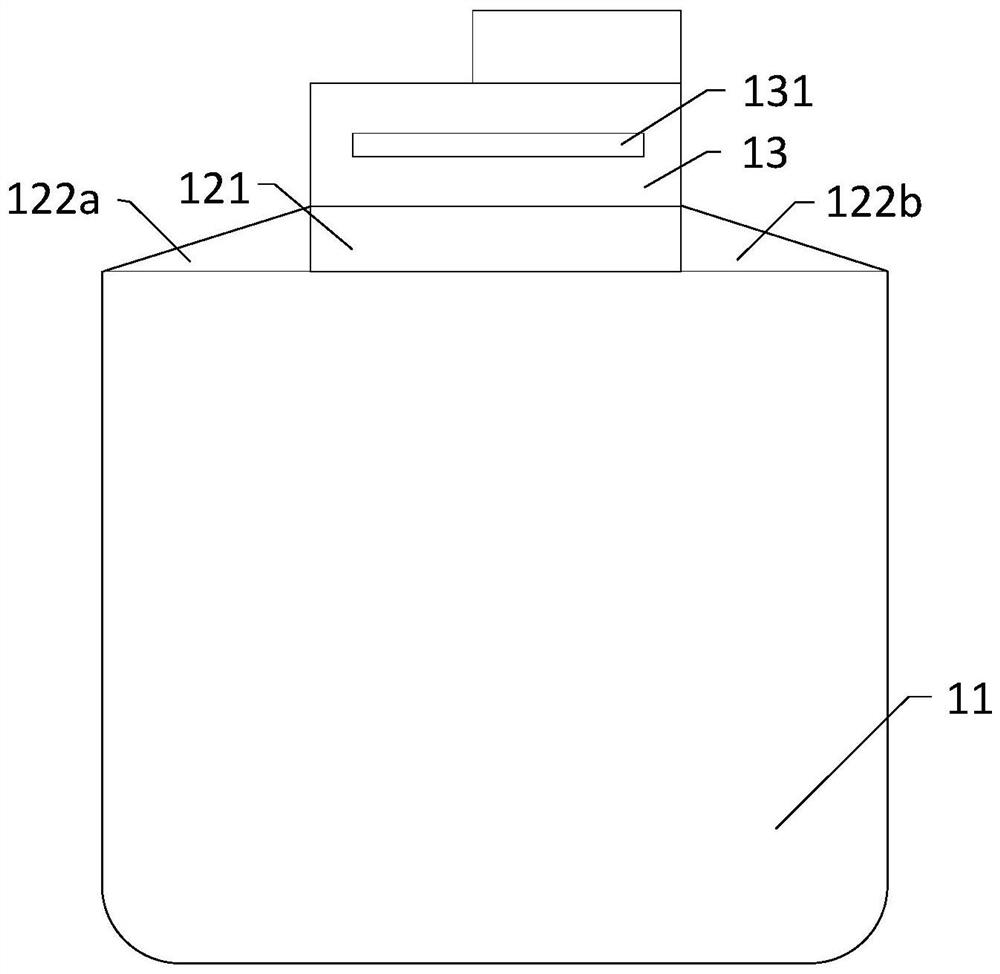
The invention discloses a display panel and an electronic device. The display panel comprises a flexible display panel which comprises a display region and a bending region disposed outside the display region. The display region and the bending region are of an integrated structure, the bending area is provided with a bending part and a bending protection part, and a metal wire is arranged in thebending part. The bending protection cloth is distributed at the two sides of the bending part, and the bending part and the bending protection part are of an integrated structure. According to the embodiment of the invention, the bending protection part is additionally arranged in the bending area, the bending protection part is provided with the plurality of protection part metal wires, and themetal wires in the bending protection cloth are used for improving the local stress borne by the source and drain metal wires of the bending part during bending, so that the stress concentration coefficient of the metal wires in the bending area during bending is reduced, and accordingly the phenomenon that the source and drain metal wires in the bending area are broken is improved, the bending resistance is improved, and the production yield of products is improved.

Description

technical field [0001] Embodiments of the present invention relate to the field of display technology, and in particular, to a display panel and electronic equipment. Background technique [0002] With the continuous development of communication technology and the popularization and application of electronic devices such as smart phones, tablet computers and notebook computers, electronic devices are developing in the direction of diversification and personalization, and have increasingly become indispensable electronic devices in people's life and work. , Nowadays, electronic devices such as mobile phones and tablet computers have become electronic devices that people carry with them every day. At present, the flexible display market is developing rapidly. Both international panel manufacturers and smartphone manufacturers are seizing the opportunity to vigorously develop flexible display screens. The folding screen mobile phones in the future development direction of mobil...

Claims


Application Information

Patent Timeline
IPC IPC(8): H01L23/00H01L27/12G09F9/30
CPCH01L23/562H01L27/1244G09F9/301Y02E10/549
Inventor 文松贤
Owner WUHAN CHINA STAR OPTOELECTRONICS SEMICON DISPLAY TECH CO LTD
Learn More