Low-fault physical heat dissipation buried transformer substation

A fault physics, substation technology, applied in the field of substations, can solve the problems of heat dissipation, high maintenance cost, energy loss, etc., to achieve good heat dissipation effect and prevent damage.

Active Publication Date: 2021-02-23
浙江江山博奥电气有限公司
View PDF7 Cites 6 Cited by
  • Summary
  • Abstract
  • Description
  • Claims
  • Application Information

AI Technical Summary

Problems solved by technology

[0002] The buried substation is to bury the traditional box-type substation and semi-buried box-type substation completely below the ground. The ground does not affect the use. It has the advantages of saving land, improving land utilization and reducing infrastructure investment. The problem of heat dissipation is caused by the
[0003] The traditional heat dissipation structure is to set up louvers at the bottom of the high and low pressure chamber, and use an axial flow fan to exhaust the air on one side. Although it also plays a role in heat dissipation, the disadvantage is that the air inlet and outlet are in parallel positions, and most of the cold air passes through when it enters from the other side. The axial flow fan is directly discharged without entering the pit for heat circulation, and the use of too many electrical equipment for heat dissipation not only greatly causes energy loss, but also the electrical equipment is easily damaged and the maintenance cost is high. Therefore, it is necessary to provide a low-failure physical heat dissipation Buried substation to solve the problem

Method used


Image

  • Low-fault physical heat dissipation buried transformer substation
  • Low-fault physical heat dissipation buried transformer substation
  • Low-fault physical heat dissipation buried transformer substation

Examples


Embodiment

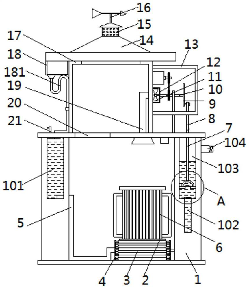
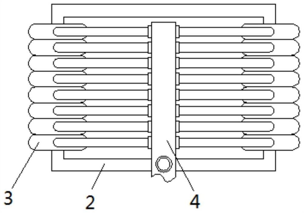
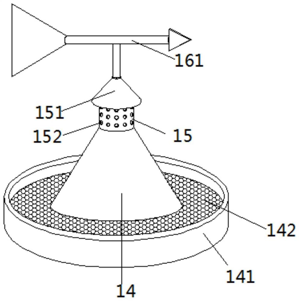
[0030] as attached figure 1 to attach Figure 7 Shown: an underground substation with low failure and physical heat dissipation, including box transformer 1, substation equipment 6, cooling box 17, and through slot 20. There is a through slot 20 on the center side of the top of box transformer 1, and the top of box transformer 1 is located at The upper end of the channel 20 is fixedly connected with a heat dissipation box 17, the top of the heat dissipation box 17 is fixedly connected with a rain-shielding water collection cover 14, and the top of the rain-shielding water collection cover 14 is fixedly connected with an air inlet tube 15, and the center of the top of the air inlet tube 15 is movably connected with a wind direction Device 16, the inside of cooling box 17 is fixedly connected with exhaust pipe 19 on the side away from No. 1 water chamber 101, the bottom of exhaust pipe 19 extends to the inside of box transformer 1 and is fixedly connected with an air inlet cover...


PUM


Abstract

The invention provides a low-fault physical heat dissipation buried transformer substation which comprises a box-type transformer substation, a heat dissipation box and a through groove. The through groove is formed in one side of the center of the top of the box-type transformer substation, the heat dissipation box is fixedly connected to the top of the box-type transformer substation and locatedat the upper end of the through groove, and the top of the heat dissipation box is fixedly connected with a rain-shielding water-collecting cover; and the top of the rain-shielding water-collecting cover is fixedly connected with an air inlet cylinder, and a wind direction device is movably connected to a top center of the air inlet cylinder. According to the low-fault physical heat dissipation buried transformer substation, a wind vane rotates under the influence of wind power, a wind deflector is obliquely arranged and located on the same horizontal line with the head-tail direction of thewind vane, and therefore after the wind vane rotates to one side of the wind direction, the wind deflector corresponds to one side of the wind direction; and a wind shield is connected with the innerwalls of the air inlet cylinders on two windless sides to block air inlet holes in the windless sides, convection is formed on the two sides of the wind deflector, natural wind blows down cold air along the inclined surface of the wind deflector, the cold air enters the heat dissipation box and the box-type transformer substation and is guided out through an exhaust pipe, and therefore heat is rapidly guided out, and the heat dissipation effect is good.

Description

technical field [0001] The invention relates to the technical field of substations, in particular to an underground substation with low failure and physical heat dissipation. Background technique [0002] The buried substation is to bury the traditional box-type substation and semi-buried box-type substation completely below the ground. The ground does not affect the use. It has the advantages of saving land, improving land utilization and reducing infrastructure investment. The bottom leads to the problem of heat dissipation. [0003] The traditional heat dissipation structure is to set up louvers at the bottom of the high and low pressure chamber, and use an axial flow fan to exhaust the air on one side. Although it also plays a role in heat dissipation, the disadvantage is that the air inlet and outlet are in parallel positions, and most of the cold air passes through when it enters from the other side. The axial flow fan is directly discharged without entering the pit f...

Claims


Application Information

Patent Timeline
Patent Type & Authority Applications(China)
IPC IPC(8): H02B1/56H02B7/08H02B1/46H02B1/28
CPCH02B1/56H02B7/08H02B1/46H02B1/28
Inventor 郑春余
Owner 浙江江山博奥电气有限公司
Why Eureka
Try Eureka