Electrical cabinet dust removal device

A technology for dust removal devices and electrical cabinets, applied in the directions of electrical components, electrical equipment structural parts, support structure installation, etc., can solve the problems of time-consuming and labor-intensive, low efficiency, increase labor intensity of workers, etc., and achieve the effect of sufficient cleaning

Active Publication Date: 2021-02-23
盐城电力设计院有限公司
View PDF12 Cites 2 Cited by
  • Summary
  • Abstract
  • Description
  • Claims
  • Application Information

AI Technical Summary

Problems solved by technology

[0005] In order to overcome the time-consuming and labor-intensive manual cleaning, and the need to suspend the operation of the electrical cabinet before cleaning, the efficiency is relatively low, and the labor intensity of the w

Method used


Image

  • Electrical cabinet dust removal device
  • Electrical cabinet dust removal device
  • Electrical cabinet dust removal device

Examples


Embodiment 1

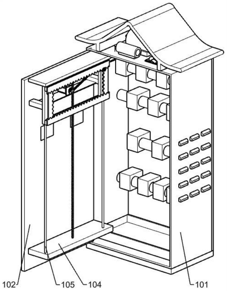
[0027] A dust removal device for electrical cabinets, such as Figure 1-8 As shown, it includes an electrical cabinet body 101, an electrical cabinet door 102, a door shaft 103, a support plate 104, a support column 105, a power assembly 2a, a moving mechanism 2b, a cleaning mechanism 2c and a switching mechanism 3, the electrical cabinet body 101 and the door shaft 103 rotating connection, the electrical cabinet door 102 is fixedly connected to the door shaft 103, there are two support plates 104, which are fixedly connected to the upper and lower parts of the inner side of the electrical cabinet door 102, and there are two support columns 105, which are fixedly connected on the two support plates 104 Between them, the power assembly 2a is slidably connected to two supporting columns 105, the moving mechanism 2b is arranged on the power assembly 2a, the cleaning mechanism 2c is arranged on the moving mechanism 2b, and the switching mechanism 3 is arranged on the electrical cab...

Embodiment 2

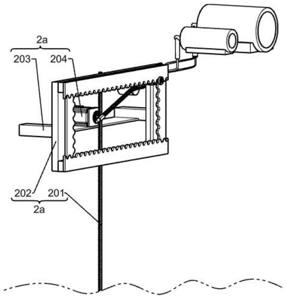
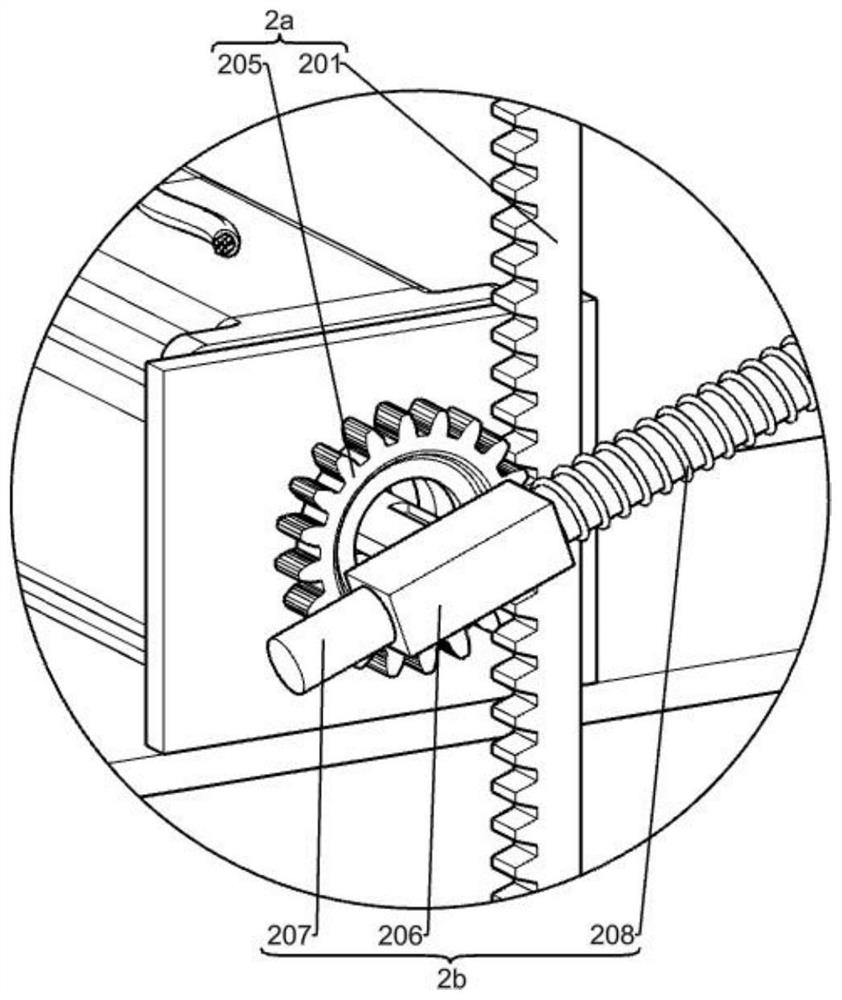
[0030] On the basis of Example 1, such as Figure 2-4 As shown, the power assembly 2a includes a first rack 201, a rectangular frame 202, a support frame 203, a motor 204 and a pinion 205, the first rack 201 is fixedly connected between two support plates 104, and the two sides of the rectangular frame 202 Covered on two supporting columns 105, the rectangular frame 202 is fixedly connected with the supporting frame 203, the supporting frame 203 is fixedly connected with a motor 204, and the output shaft of the motor 204 is fixedly connected with a pinion gear 205.

[0031] When the output shaft of the motor 204 starts to rotate, the pinion 205 is driven to rotate, and the pinion 205 meshes with the first rack 201 to drive the support frame 203 to slide up and down along the support column 105, thereby driving the rectangular frame 202 to slide up and down.

[0032] The moving mechanism 2b includes a rotating block 206, a connecting rod 207, a spring 208, a first rotating shaf...

Embodiment 3

[0035] On the basis of Example 2, such as Figure 5-8 As shown, the dust removal mechanism includes an extension spring 214, a connecting block 215, a ball groove 216, a spherical control rod 217 and a shower nozzle 218. There are four extension springs 214, which are fixedly connected on the four inner walls of the slider 210, and the four sides of the connecting block 215 It is fixedly connected with four extension springs 214, and the connecting block 215 is provided with a ball groove 216, and the ball groove 216 is connected with a spherical control rod 217 in rotation, and the other end of the spherical control rod 217 is fixedly connected on the inner wall of the slider 210, and the nozzle 218 Fixedly connected to the connection block 215, the nozzle 218 is provided with three circular openings, and the three circular openings are respectively the mist port 219, the flushing port 220 and the fan port 221, the mist port 219 is a small hole with a large diameter, and the f...


PUM


Abstract

The invention relates to a dust removal device, and particularly relates to an electrical cabinet dust removal device. The technical problem is to provide the electrical cabinet dust removal device which can automatically clean the electrical cabinet and can clean the electrical cabinet without power failure. The electrical cabinet dust removal device comprises an electrical cabinet body, an electrical cabinet door, a door spindle, supporting plates, supporting columns, a power assembly and the like. The electrical cabinet body is rotatably connected with the door spindle, the electrical cabinet door is fixedly connected to the door spindle, the two supporting plates are fixedly connected to the upper portion and the lower portion of the inner side of the electrical cabinet door, the two supporting columns are fixedly connected between the two supporting plates, and the power assembly is slidably connected to the two supporting columns. Through a reciprocating mechanism and a moving mechanism, a cleaning mechanism is driven to automatically move up and down in the electrical cabinet and can continuously move around a small circle so that each position in the electrical cabinet canbe cleaned.

Description

technical field [0001] The invention relates to a dust removal device, in particular to an electric cabinet dust removal device. Background technique [0002] The electrical cabinet is a cabinet made of steel to protect the normal operation of components. Electrical cabinets are widely used mainly in chemical industry, environmental protection industry, power system, metallurgical system, industry, nuclear power industry, fire safety monitoring, transportation industry, etc. The electrical cabinet generates a lot of heat during use. To dissipate heat, heat dissipation ports are generally provided on the surface of the cabinet. However, a large amount of dust will be deposited in the electrical cabinet after long-term use, which will affect the conductivity of the components in the electrical cabinet and affect the normal operation of the electrical cabinet. use, and it is easy to cause aging of electrical components. In severe cases, it will cause a short circuit and burn o...

Claims


Application Information

Patent Timeline
IPC IPC(8): H05K5/02H05K7/14H05K7/20B08B3/02B08B5/02
CPCB08B3/024B08B5/02H05K5/02H05K7/14H05K7/20136
Inventor 程新钟
Owner 盐城电力设计院有限公司
Why Eureka
Try Eureka