A potato agricultural product processing device

A technology for processing agricultural products and potatoes, which is applied in the field of processing devices for potato agricultural products. It can solve the problems of complex structure, damage, and large size, and achieve the effects of reducing the cleaning process, speeding up the peeling process, and reducing labor intensity.

Active Publication Date: 2021-11-30
青岛康福莱现代农业科技有限公司
View PDF0 Cites 0 Cited by
  • Summary
  • Abstract
  • Description
  • Claims
  • Application Information

AI Technical Summary

Problems solved by technology

[0005] In order to overcome the low efficiency of the manual peeling process and the fact that the peeling is not clean, it is difficult to ensure the cleanliness of the vegetables due to human hands touching all parts of the vegetables during the peeling process. , peeling knives are easy to cause damage to people's hands. Vegetable peeling machines are used in larger factories. The existing vegetable peeling machines are large in size and complex in structure. They are mostly used for industrial vegetable processing and are not suitable for small The shortcoming of batch peeling process, the technical problem of the present invention is: provide a kind of simple in structure, automatic feeding and peeling small-batch potato agricultural product peeling device

Method used


Image

  • A potato agricultural product processing device
  • A potato agricultural product processing device
  • A potato agricultural product processing device

Examples


Embodiment 1

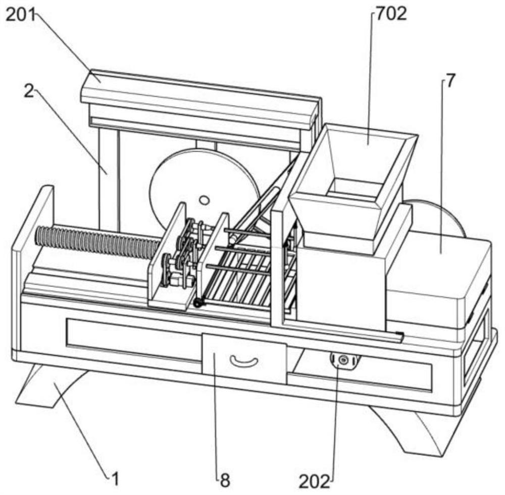
[0031] A potato agricultural product processing device, such as Figure 1-6Shown, comprise frame 1, the first support plate 2, the first slide frame 201 and feed box 8, three first support plates 2 are fixedly installed on the upper rear side of frame 1, the first slide frame 201 and three The upper end of the first support plate 2 is fixedly connected, and the material box 8 is fixedly installed in the middle position of the frame 1, and is characterized in that: it also includes: a power mechanism, a rotating mechanism and a peeling mechanism, and the power mechanism is fixedly installed on the frame 1 The rear part, the rotating mechanism is fixedly installed in the upper middle position of the frame 1, and the peeling mechanism is slidably installed in the upper middle position of the frame 1 on the right side, the peeling mechanism is connected with the power mechanism, and the peeling mechanism is connected with the rotating mechanism.

[0032] Working principle: When pr...

Embodiment 2

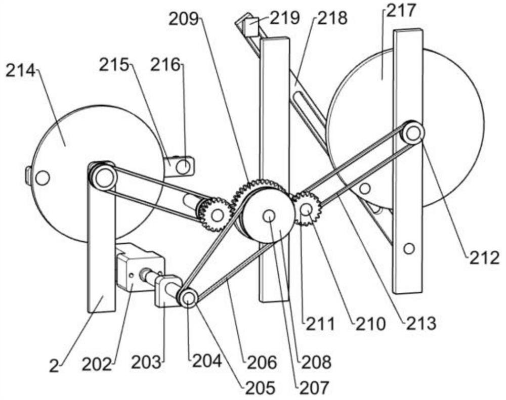
[0034] On the basis of Example 1, such as figure 2 As shown, the power mechanism includes a first motor 202, a support block 203, a first shaft 204, a first pulley 205, a first belt 206, a second shaft 207, a second pulley 208, a missing tooth gear 209, The third shaft rod 210, the first spur gear 211, the third pulley 212, the second belt 213 and the reciprocating mechanism, the first motor 202 is fixedly installed on the right rear side of the middle part of the frame 1, and the support block 203 is fixedly installed on On the right rear side of the middle part of the frame 1, the front end of the first shaft rod 204 is fixedly installed on the output shaft of the first motor 202, the first shaft rod 204 is rotationally connected with the support block 203, and the first pulley 205 is fixedly installed on the The rear end of the first axle bar 204, the front end of the second axle bar 207 is rotatably installed on the rear upper side of the frame 1, the second pulley 208 is...

Embodiment 3

[0043] On the basis of Example 2, such as Figure 7 As shown, a turning mechanism is also included, and the turning mechanism includes an L-shaped plate 5, a gear bar 501, a fifth shaft 502, a second spur gear 503, a bevel gear 504, a sixth shaft 505 and a bracket 506, and the L-shaped plate The left side of the rear portion of 5 is fixedly connected with the slide frame 4, the lower side of the L-shaped plate 5 is slidably connected with the frame 1, the gear bar 501 is fixedly installed on the upper right side of the L-shaped plate 5, and the fifth shaft rod 502 is rotatably installed on the On the lower side of the fixed plate 312, the second spur gear 503 is fixedly installed on the front end of the fifth shaft 502, a bevel gear 504 is fixedly installed on the front side of the fifth shaft 502, and the bracket 506 is installed in the slot opened on the frame 1 Inside, a sixth shaft 505 is fixedly installed on the front side of the bracket 506, the sixth shaft 505 is rotati...


PUM


Abstract

The invention relates to the field of agricultural product processing, in particular to a potato agricultural product processing device. The technical problem of the present invention is to provide a small-batch potato agricultural product peeling device with simple structure, automatic feeding and peeling. A processing device for potato agricultural products, comprising a frame, a first support plate, a first slide frame, a material box, a power mechanism, etc.; three first support plates are fixedly installed on one side of the frame, and the first slide frame and One side of the three first support plates away from the frame is fixedly connected, the material box is fixedly installed in the middle of the frame, and the power mechanism is fixedly installed on the side of the frame close to the first support plate. In the present invention, the vegetables are inserted into the second rotating rod for rotation through the rotating mechanism, which replaces manual hand-held vegetables, and effectively avoids damage to human hands during the peeling process.

Description

technical field [0001] The invention relates to the field of agricultural product processing, in particular to a potato agricultural product processing device. Background technique [0002] With the improvement of dietary life and the increase of people's demand for vegetables, in order to ensure a large amount of high-quality output of vegetables, farmers will put pesticides on vegetables, so that pesticides will remain on the surface of vegetables, and it will definitely require a lot of cleaning to clean them. water, polluting the water resource environment. [0003] The traditional process of manual peeling is generally to manually remove the outer skin of the vegetables bit by bit by holding the vegetables in one hand and a peeling knife in the other. The efficiency of the manual peeling process is too low, and the peeling is not clean. In the process of peeling, it is difficult to ensure the cleanliness of vegetables because human hands touch all parts of vegetables. ...

Claims


Application Information

Patent Timeline
Patent Type & Authority Patents(China)
IPC IPC(8): A23N7/02A23N15/00
CPCA23N7/026A23N15/00A23N2015/008
Inventor 李美霞
Owner 青岛康福莱现代农业科技有限公司
Why Eureka
Try Eureka