A system and method for removing carbon monoxide and denitrification from flue gas
A carbon monoxide and denitration technology, applied in chemical instruments and methods, separation methods, gas treatment, etc., can solve the problems of catalyst deactivation and poor sulfur resistance, and achieve the effect of reducing pollution and avoiding secondary pollution.
- Summary
- Abstract
- Description
- Claims
- Application Information
AI Technical Summary
Problems solved by technology
Method used
Image
Examples
Embodiment 1
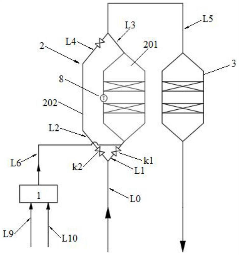
[0102] Such as figure 1 As shown, a system for removing carbon monoxide and denitrification from flue gas, the system includes a hot blast stove 1, a CO reactor 2, and an SCR reactor 3. The CO reactor 2 includes a main reaction tower 201 and a bypass 202 . The first pipeline L1 and the second pipeline L2 branched from the raw flue gas transmission pipeline L0 are respectively connected to the main reaction tower 201 and the bypass 202 of the CO reactor 2 . Both the third pipeline L3 drawn from the flue gas outlet of the main reaction tower 201 of the CO reactor 2 and the fourth pipeline L4 drawn from the bypass 202 of the CO reactor 2 are connected to the SCR reaction via the fifth pipeline L5 after being combined. Device 3. The hot blast outlet of the hot blast stove 1 is connected to the first pipeline L1 via the sixth pipeline L6. A second temperature detection device 8 is provided on the side wall of the main reaction tower 201 of the CO reactor 2 .
Embodiment 2
[0104] Embodiment 1 is repeated, except that the system further includes a first valve k1 arranged on the first pipeline L1. The first valve k1 is located upstream of the position where the sixth pipeline L6 is connected to the first pipeline L1. The system also includes a second valve k2 arranged on the second pipeline L2. The system also includes a gas delivery pipeline L9 connected to the supplementary gas inlet of the hot blast stove 1 . The system also includes a combustion-supporting gas delivery pipeline L10, which is connected to the supplementary combustion-supporting gas inlet of the hot blast stove 1 .
Embodiment 3
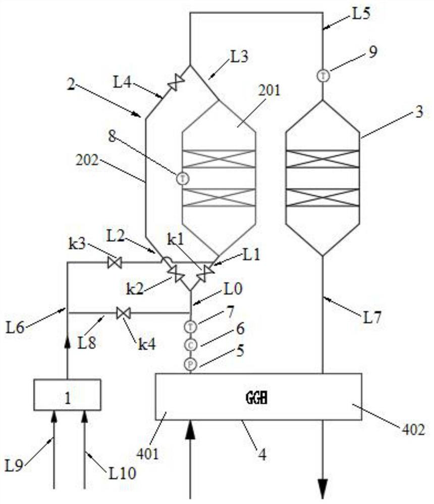
[0106] Such as figure 2 As shown, Example 2 is repeated, except that the system also includes a GGH heat exchanger 4 . The raw flue gas is connected to the flue gas inlet of the first heat exchange area 401 of the GGH heat exchanger 4 through pipes, and the flue gas outlet of the first heat exchange area 401 of the GGH heat exchanger 4 is connected to the raw flue gas transmission pipeline L0, and the SCR The net flue gas outlet of the reactor 3 is connected to the second heat exchange area 402 of the GGH heat exchanger 4 through the seventh pipe L7.
PUM
 Abstract
Description
Claims
Application Information
 - R&D
- Intellectual Property
- Life Sciences
- Materials
- Tech Scout
- Unparalleled Data Quality
- Higher Quality Content
- 60% Fewer Hallucinations
Browse by: Latest US Patents, China's latest patents, Technical Efficacy Thesaurus, Application Domain, Technology Topic, Popular Technical Reports.
© 2025 PatSnap. All rights reserved.Legal|Privacy policy|Modern Slavery Act Transparency Statement|Sitemap|About US| Contact US: help@patsnap.com


