Proportioning and stirring equipment for blending chemical reagents
A technology of stirring equipment and chemical reagents, which is applied in the direction of mixer accessories, chemical instruments and methods, chemical/physical processes, etc., which can solve the problems of cumbersome operation, manual control, and inconvenient cleaning of the box, so as to ensure the deployment effect and uniform pouring , easy to clean effect
- Summary
- Abstract
- Description
- Claims
- Application Information
AI Technical Summary
Problems solved by technology
Method used
Image
Examples
Embodiment 1
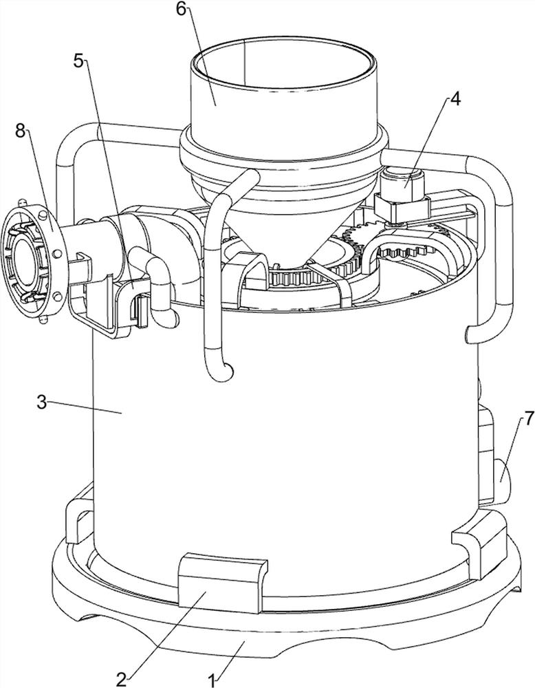
[0027] A kind of proportioning mixing equipment for chemical reagent deployment, such as Figure 1-3 As shown, it includes a base 1, a support frame 2, a mixing bucket assembly 3 and a stirring mechanism 4. The top of the base 1 is connected with a plurality of support frames 2 evenly spaced, and a mixing bucket assembly 3 is connected between the multiple support frames 2. A stirring mechanism 4 is installed on the bucket assembly 3 .
[0028] The mixing barrel assembly 3 includes a barrel body 31, a first positioning ring frame 32, a delivery pipe 33 and a bracket 34, a barrel body 31 is connected between the tops of the multi-block support frame 2, and a first positioning frame is connected to the upper left side of the barrel body 31. The ring frame 32, the first positioning ring frame 32 is equipped with a delivery pipe 33, and the top of the barrel body 31 is connected with a bracket 34.
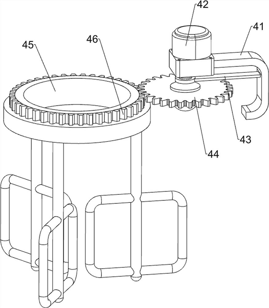
[0029] The stirring mechanism 4 includes a first fixed mount 41, a servo motor 42...
Embodiment 2
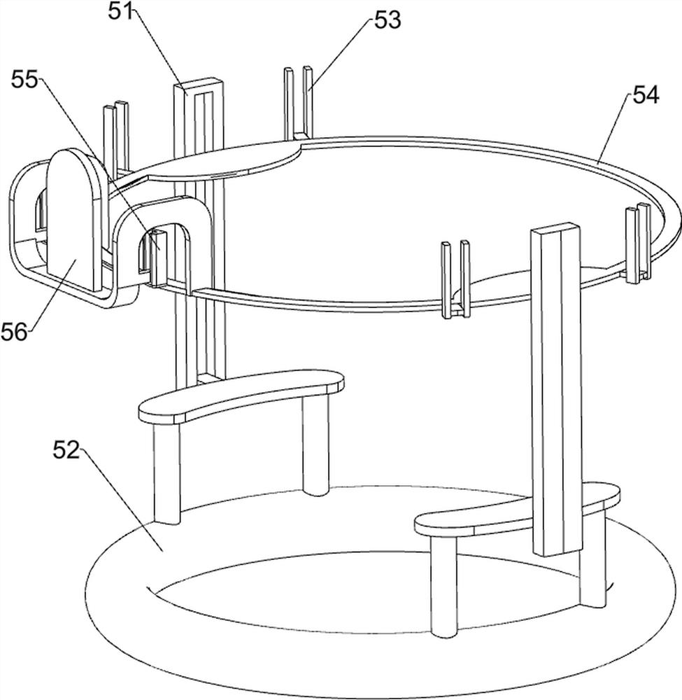
[0032] On the basis of Example 1, such as Figure 4-5 Shown, also comprise water stop mechanism 5, water stop mechanism 5 comprises first guide rail frame 51, floating ring frame 52, second guide rail frame 53, sliding frame 54, the 3rd guide rail frame 55 and dividing plate 56, staving The front and rear side walls in the 31 are connected with a first guide rail frame 51, and a floating ring frame 52 is slidably connected between the first rail frames 51 on both sides. Rail frame 53, two second rail frames 53 are left-right symmetrical, and slide frame 54 is connected with sliding type between four second rail frames 53, and the left upper part of staving 31 is connected with the 3rd rail frame 55, and the 3rd rail frame The frame 55 is slidably connected with a dividing plate 56, the dividing plate 56 is connected with the sliding frame 54, the bottom of the conveying pipe 33 has a socket, and one end of the dividing plate 56 is located in the socket.
[0033] When the chem...
Embodiment 3
[0037] On the basis of Example 2, such as Figure 6-7As shown, a liquid discharge mechanism 7 is also included. The liquid discharge mechanism 7 includes a discharge pipe 71, a mounting seat 72 and an elastic baffle 73. The right side of the bottom of the barrel body 31 is connected with a discharge pipe 71. On the discharge pipe 71 A mounting seat 72 is connected, and an elastic baffle 73 is slidably connected to the mounting seat 72 , and the elastic baffle 73 cooperates with the discharge pipe 71 .
[0038] When it is necessary to pour out the chemical reagent stirred in the barrel body 31, pull the sliding frame 54 with one hand so that the partition plate 56 and the blocking ball 64 block the delivery pipe 33 and the storage barrel 62 respectively, and the other pulls the elastic baffle 73 Move upwards, the discharge pipe 71 is not blocked, so that the chemical reagent in the barrel body 31 flows out from the discharge pipe 71, when the chemical reagent in the barrel body...
PUM
 Abstract
Description
Claims
Application Information
 - R&D
- Intellectual Property
- Life Sciences
- Materials
- Tech Scout
- Unparalleled Data Quality
- Higher Quality Content
- 60% Fewer Hallucinations
Browse by: Latest US Patents, China's latest patents, Technical Efficacy Thesaurus, Application Domain, Technology Topic, Popular Technical Reports.
© 2025 PatSnap. All rights reserved.Legal|Privacy policy|Modern Slavery Act Transparency Statement|Sitemap|About US| Contact US: help@patsnap.com


