Pulverizing device for calcium carbonate
A technology for grinding and pulverizing calcium carbonate into powder, applied in solid separation, cement production, chemical instruments and methods, etc. The effect of improving grinding efficiency
- Summary
- Abstract
- Description
- Claims
- Application Information
AI Technical Summary
Problems solved by technology
Method used
Image

Examples
Embodiment 1
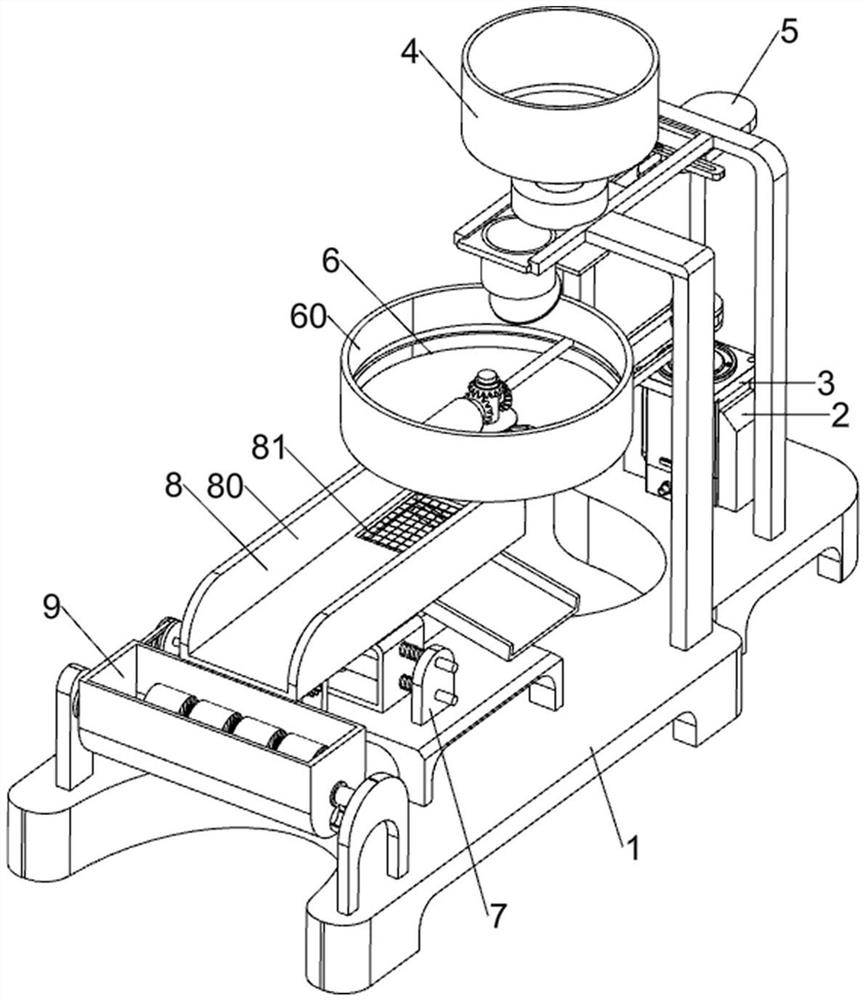
[0082] A device for grinding calcium carbonate into powder, such as figure 1 As shown, it includes a base 1, a first fixed block 2, a servo motor 3, a pushing mechanism 5, and a rolling mechanism 6. The top right side of the base 1 is symmetrically provided with a first fixed block 2, and between the first fixed blocks 2 is a The servo motor 3 is provided with a pushing mechanism 5 on the right side of the top of the base 1, and a rolling mechanism 6 is provided on the right side of the top of the base 1.
[0083] The staff puts calcium carbonate in the rolling mechanism 6, and then starts the servo motor 3 to work, and the servo motor 3 drives the rolling parts of the rolling mechanism 6 to rotate through the pushing mechanism 5, thereby grinding the calcium carbonate and rolling it into The calcium carbonate powder of powder falls from rolling mechanism 6, and now the staff can collect under rolling mechanism 6, and after all calcium carbonate is rolled into powder, close se...
Embodiment 2
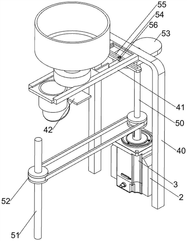
[0085] On the basis of Example 1, such as figure 2 and Figure 4 As shown, the pushing mechanism 5 includes a first rotating shaft 50, a second rotating shaft 51, a first pulley assembly 52, a rotating plate 53, a second connecting rod 54, a guide plate 55 and a third connecting rod 56, and the output end of the servo motor 3 is provided There is a first rotating shaft 50, the top of the first rotating shaft 50 is provided with a rotating plate 53, the left side of the rotating plate 53 top is provided with a second connecting rod 54, and the sliding type on the second connecting rod 54 is provided with a guide plate 55, and the left side of the guiding plate 55 A third connecting rod 56 is provided, a second rotating shaft 51 is rotatably provided at the top middle of the base 1 , and a first pulley assembly 52 is provided between the first rotating shaft 50 and the second rotating shaft 51 .
[0086] The rolling mechanism 6 includes a rolling basket 60, a first connecting ...
Embodiment 3
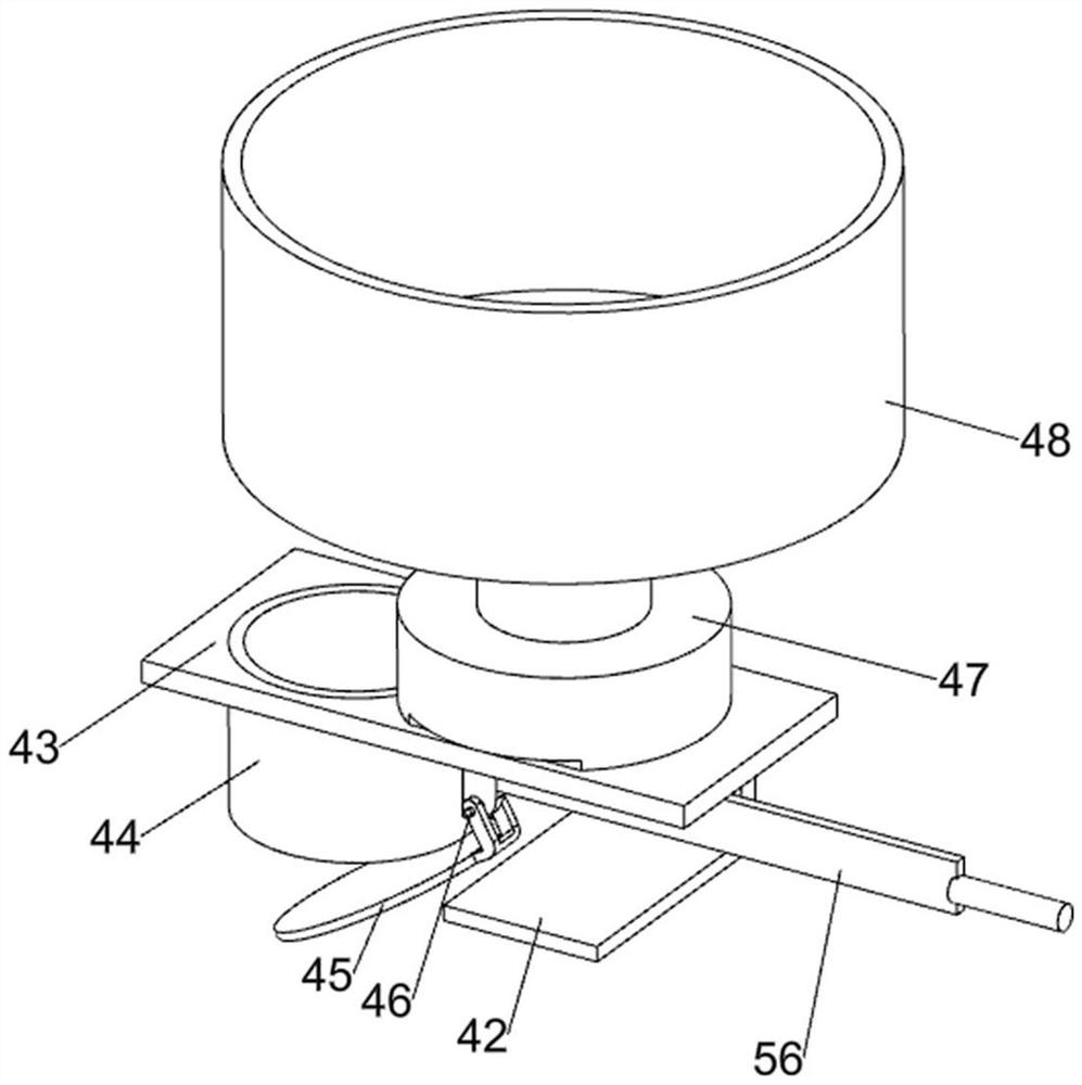
[0089] On the basis of Example 2, such as figure 2 , image 3 , Figure 5-7 As shown, it also includes a blanking mechanism 4, and the blanking mechanism 4 includes a support frame 40, a slide rail 41, a baffle plate 42, a slide plate 43, a discharge bucket 44, a cover 45, a first connecting rod 46, and a blanking tube 47 and the discharge basket 48, the right side of the top of the base 1 is provided with a support frame 40, the left side of the support frame 40 top is symmetrically provided with a slide rail 41, the bottom of the slide rail 41 on the rear side is provided with a baffle plate 42, and slides between the slide rails 41 The type is provided with a slide plate 43, the bottom left side of the slide plate 43 is provided with a discharge bucket 44, the discharge bucket 44 is connected with the third connecting rod 56, and the lower part of the right side of the discharge bucket 44 is provided with a first connecting rod 46, and the first connecting rod 46 upper r...
PUM
 Abstract
Description
Claims
Application Information
 - R&D
- Intellectual Property
- Life Sciences
- Materials
- Tech Scout
- Unparalleled Data Quality
- Higher Quality Content
- 60% Fewer Hallucinations
Browse by: Latest US Patents, China's latest patents, Technical Efficacy Thesaurus, Application Domain, Technology Topic, Popular Technical Reports.
© 2025 PatSnap. All rights reserved.Legal|Privacy policy|Modern Slavery Act Transparency Statement|Sitemap|About US| Contact US: help@patsnap.com