
Numerically-controlled machine tool material bin feeding and discharging lifting device

A technology of CNC machine tools and lifting devices, which is applied in metal processing and other directions, can solve the problems of products that cannot bear heavy weight and increase the labor intensity of staff, and achieve the effects of convenient loading and unloading, reducing labor intensity and convenient operation

Pending Publication Date: 2021-02-26
沈机智享(东台)科技有限公司
View PDF1 Cites 0 Cited by
  • Summary
  • Abstract
  • Description
  • Claims
  • Application Information

AI Technical Summary

Problems solved by technology

However, in the comparison document, only the motor drives the lifting guide rod and the pallet to move through the chain, which cannot bear heavy products, which will reduce the number of products to be loaded, and require the staff to add raw materials frequently, thus increasing the work. The labor intensity of personnel, so we propose a CNC machine tool hopper loading and unloading lifting device to solve the above problems

Method used


Image

  • Numerically-controlled machine tool material bin feeding and discharging lifting device
  • Numerically-controlled machine tool material bin feeding and discharging lifting device
  • Numerically-controlled machine tool material bin feeding and discharging lifting device

Examples


Embodiment Construction

[0020]The technical solutions in the embodiments of the present invention will be clearly and completely described below in conjunction with the accompanying drawings in the embodiments of the present invention. Obviously, the described embodiments are only a part of the embodiments of the present invention, rather than all the embodiments. Based on the embodiments of the present invention, all other embodiments obtained by those of ordinary skill in the art without creative work shall fall within the protection scope of the present invention.

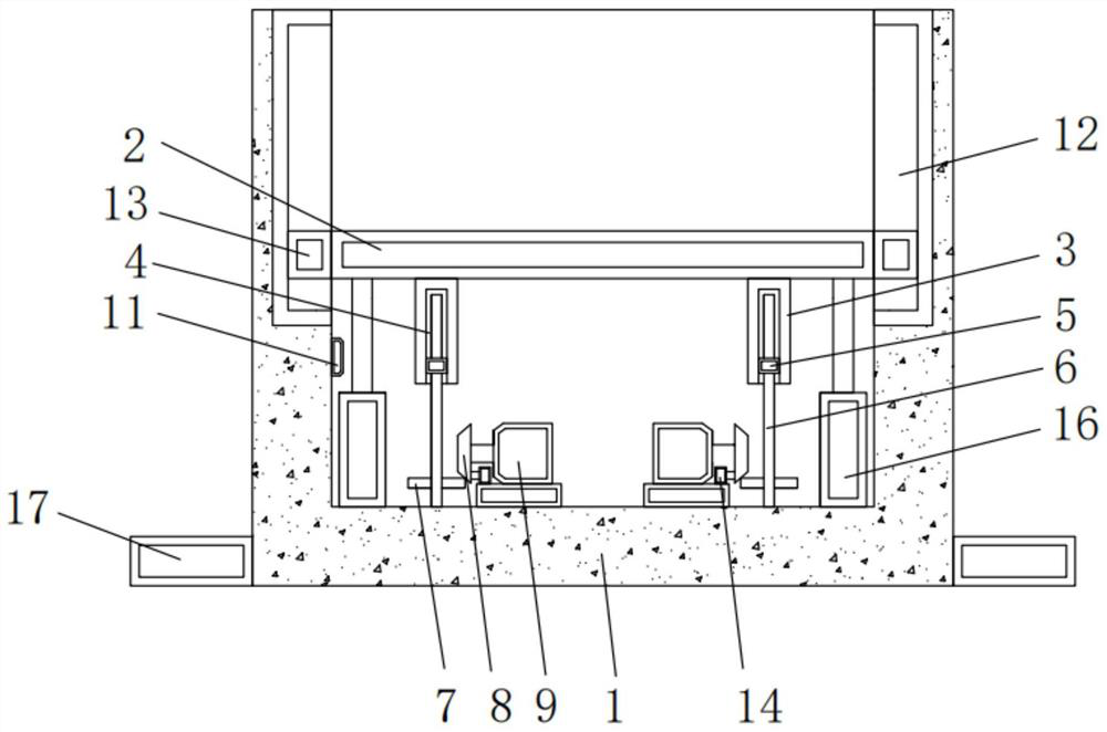
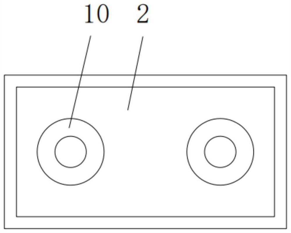
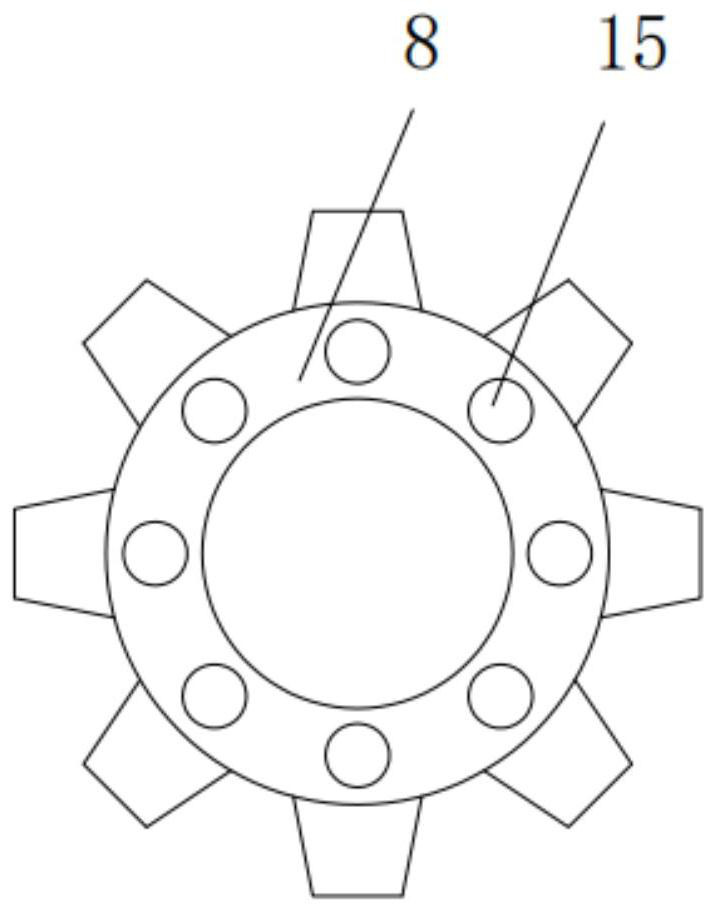
[0021]The present invention provides such asFigure 1-4The illustrated CNC machine tool silo loading and unloading device includes a rectangular silo 1. A placement plate 2 is arranged inside the rectangular silo 1, and a bottom surface of the placement plate 2 is fixedly connected to support rods 3 at symmetrical positions on the left and right sides. , The bottom surface of the supporting rod 3 is provided with a rectangular groove 4, the insi...


PUM


Abstract

The invention discloses a numerically-controlled machine tool material bin feeding and discharging lifting device. The device comprises a rectangular bin, a containing plate is arranged in the rectangular bin, supporting rods are fixedly connected to the symmetrical positions of the left side and the right side of the bottom face of the containing plate correspondingly, rectangular grooves are formed in the bottom faces of the supporting rods, nuts are fixedly connected in the rectangular grooves, the nuts are in threaded connection with lead screws, the bottom ends of the lead screws are rotationally connected with the inner bottom of the rectangular bin through bearings, the lower ends of the lead screws are connected with first gears in a clamped manner, the first gears are in engaged connection with second gears, and the second gears are arranged at the positions of the output ends of servo motors. The device can automatically control up-and-down movement of the containing plate, and therefore raw materials are lifted, and feeding and discharging are facilitated; by arranging the servo motors and the lead screws, up-and-down movement of the supporting rods can be facilitated soas to drive up-and-down movement of the containing plate; and by arranging a pressure sensor on the upper surface of the containing plate, the moving distance of the containing plate can be conveniently controlled, and the device is convenient to use.

Description

Technical field[0001]The invention belongs to the technical field of a numerical control machine tool silo, and specifically relates to a loading and unloading device for a numerical control machine tool silo.Background technique[0002]At present, the lifting device used to lift the pallet of the placed part in the automatic loading and unloading silo uses a cylinder to drive the lifting guide rod to move up and down, and its position accuracy is difficult to control, and it is easy to be unable to grasp or damage the manipulator.[0003]The Chinese patent with the application number [CN201120384103.4] contains: a CNC machine tool automatic silo loading and unloading lifting device, the lifting device includes a guide column, a pallet for placing parts, a lifting device that drives the pallet to move up and down, and The detection device is characterized in that the lifting device is composed of a fixed plate vertically fixedly installed under the bottom of the silo, two sprockets fixe...

Claims


Application Information

Patent Timeline
IPC IPC(8): B23Q7/00
CPCB23Q7/00
Inventor 郑伟黄旭松冯允伞帅范瑜
Owner 沈机智享(东台)科技有限公司
Learn More