Tilting type free half-rotating flapping rotor aircraft

A flapping rotor and free technology, applied in the field of aircraft, can solve the problems of low efficiency, poor lift stability, and poor flight flexibility of flapping rotor aircraft, and achieve the effects of improving efficiency, improving stability, and maneuvering flexibility

Inactive Publication Date: 2021-02-26
GUANGDONG GUOSHIJIAN TECH DEV CO LTD
View PDF8 Cites 0 Cited by
  • Summary
  • Abstract
  • Description
  • Claims
  • Application Information

AI Technical Summary

Problems solved by technology

[0002] The flapping rotorcraft is a novel aircraft imitating the flight of birds. It has the advantages of vertical lift-off and hovering in the air that rotorcraft and helicopters have. Part of the lift force will cancel each other out, resulting in lower efficiency of the flapping rotorcraft ri

Method used


Image

  • Tilting type free half-rotating flapping rotor aircraft
  • Tilting type free half-rotating flapping rotor aircraft
  • Tilting type free half-rotating flapping rotor aircraft

Examples


Embodiment 1

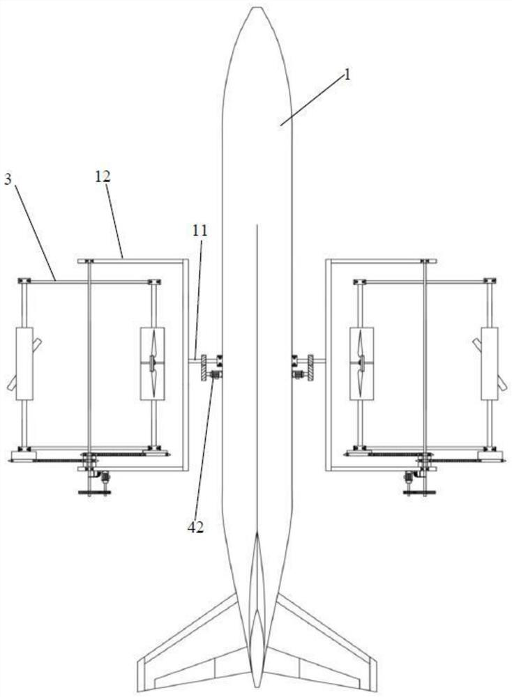
[0126] The embodiment of the present invention discloses a tilting free semi-rotating flapping rotor aircraft, comprising: a fuselage 1, a flapping rotor 3, an inclination adjustment device 42, a rotating shaft 11, a frame 12 and a controller;

[0127] Wherein, the tail portion of the fuselage 1 is provided with an empennage or a tail rotor, and the belly is provided with a landing gear, both sides of which are symmetrically connected to the rotating shaft 11 through bearing rotation, and the frame 12 is fixed on the rotating shaft 11;

[0128] The inclination adjustment device 42 is respectively connected to the fuselage 1 and the rotating shaft 11, and is electrically connected to the controller to drive the rotating shaft 11 to rotate and drive the frame 12 to tilt;

[0129] The flapping rotor 3 includes: a revolution main shaft 21, a revolution motor 22, a revolution transmission gear set 24, an autorotation transmission, an autorotation main shaft 23 and a rotor mechanism ...

Embodiment 2

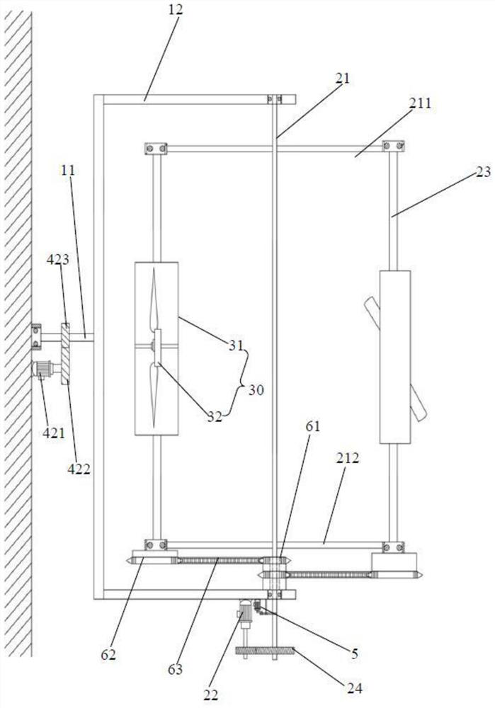
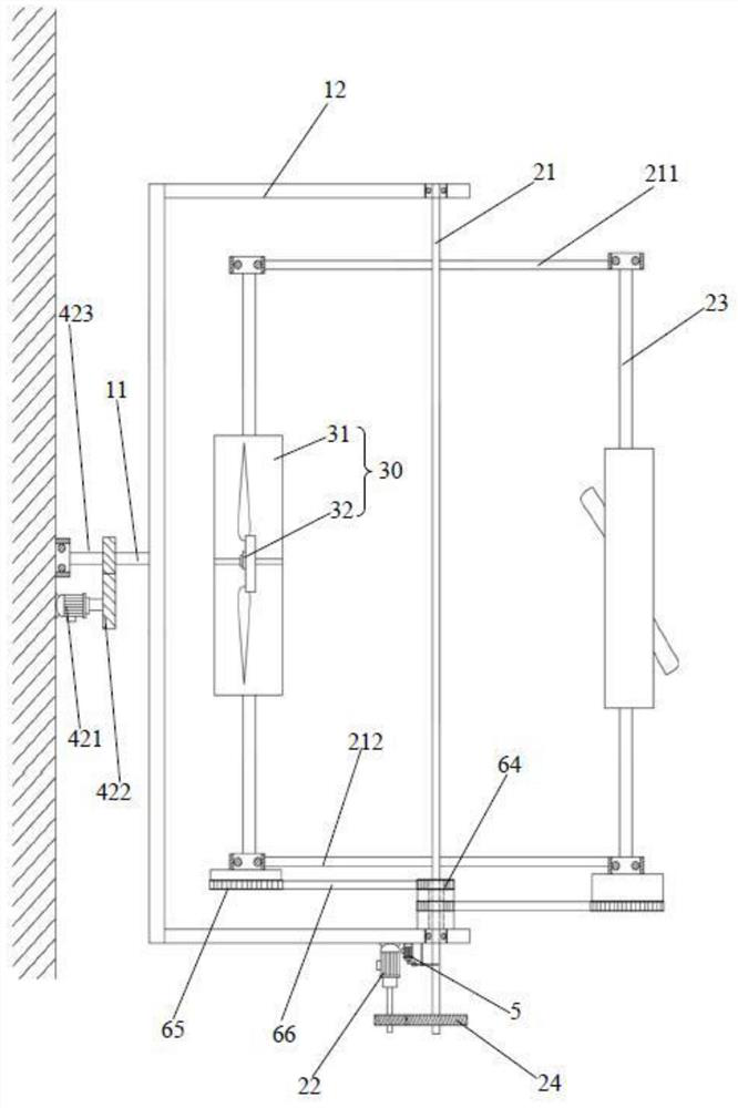
[0143] Embodiment 2 of the present invention is different from Embodiment 1 in that: the rotation transmission device is a synchronous belt transmission mechanism, and the synchronous belt transmission mechanism includes two identical central synchronous wheels 64, transmission synchronous wheels 65 and synchronous belts 66, and the central synchronous wheel 64 The diameter ratio with the transmission synchronous wheel 65 is 1:2;

[0144] The two central synchronous wheels 64 are all located between the rear pivot arm 212 and the frame 12, or between the front pivot arm 211 and the frame 12, and the end faces of the two central synchronous wheels 64 are parallel and fixed, and at the same time, one of the central synchronous The end face of wheel 64 is fixed with frame 12;

[0145] The centers of the two central synchronous wheels 64 are provided with a through hole with a diameter larger than that of the revolving main shaft 21 as a rotating space, and the shaft ends of the r...

Embodiment 3

[0148] Embodiment 3 of the present invention is different from Embodiment 1 in that: the rotation transmission device is a chain transmission mechanism, and the chain transmission mechanism includes two identical first driving bevel gears 67, second driven bevel gears 68 and torque transmission mechanisms;

[0149] The end surfaces of the two first driving bevel gears 67 are parallel and fixed, while the end surface of one of the first driving bevel gears 67 is fixed on the frame 12, and the centers of the two first driving bevel gears 67 are provided with a diameter larger than the revolving main shaft 21 The through hole is used as a turning space;

[0150] The two second driven bevel gears 68 are respectively fixed on the two self-rotating main shafts 23 in one-to-one correspondence, and the two first driving bevel gears 67 are connected to the two second driven bevel gears 68 in one-to-one correspondence through a torque transmission mechanism. .

[0151] The torque trans...


PUM


Abstract

The invention provides a tilting type free half-rotating flapping rotor aircraft. Two sides of a fuselage are symmetrically and rotatably connected with rotating shafts through bearings, and a frame is fixed on the rotating shafts; an inclination angle adjusting device is connected with the fuselage and the rotating shafts, is electrically connected with the controller, drives the rotating shaftsto rotate and drives the frame to tilt; revolution spindles of flapping rotors are arranged at the two sides of the fuselage through the frame and rotationally connected with the frame through bearings, and meanwhile the two ends of the revolution spindle at each side of the revolution spindles are rotationally connected with a front rotating arm and a rear rotating arm through bearings correspondingly. A revolution motor drives the revolution spindle to revolve for one circle through a revolution transmission gear set, and the revolution spindle drives the autorotation spindle to autorotate for half a circle through the autorotation transmission device. The tilting type free semi-rotating flapping rotor aircraft of the invention improves the rising efficiency and the flying safety.

Description

technical field [0001] The invention relates to the technical field of aircraft, and more specifically relates to a tilting free semi-rotating flapping rotor aircraft. Background technique [0002] The flapping rotorcraft is a novel aircraft imitating the flight of birds. It has the advantages of vertical lift-off and hovering in the air that rotorcraft and helicopters have. Part of the lift force will cancel each other out, resulting in lower efficiency of the flapping rotorcraft rising, while the flapping rotorcraft in the prior art has poor stability of lift, resulting in lower safety, and the flapping rotorcraft in the prior art The pulling force of forward flight cannot be changed by changing the angle of attack of the flapping rotor, resulting in poor flight flexibility. Contents of the invention [0003] The present invention aims to solve one of the above-mentioned technical problems in the prior art at least to a certain extent. [0004] In view of this, the pre...

Claims


Application Information

Patent Timeline
IPC IPC(8): B64C27/22B64C27/52B64C33/02
CPCB64C27/22B64C27/52B64C33/02
Inventor 王志成
Owner GUANGDONG GUOSHIJIAN TECH DEV CO LTD
Why Eureka
Try Eureka