Flapping-like rotor aircraft

A flapping-rotor and aircraft technology, applied in the field of flapping-rotor-like aircraft, can solve the problems of low efficiency, poor lift stability and low safety of the flapping-rotor aircraft, and achieve the effects of fast sailing, avoiding resistance and improving efficiency

Inactive Publication Date: 2021-03-05
GUANGDONG GUOSHIJIAN TECH DEV CO LTD
View PDF6 Cites 1 Cited by
  • Summary
  • Abstract
  • Description
  • Claims
  • Application Information

AI Technical Summary

Problems solved by technology

[0002] The flapping rotorcraft is a novel aircraft imitating the flight of birds. It has the advantages of vertical lift-off and hovering in the air that rotorcraft and helicopters have. Part of the lift will cancel each other out, resulting in lower efficiency of the flapping rotorcraft rise, while the flapping rotorcraft in the prior art has poor stability in generating lift, resulting in lower safety, and the flapping rotorcraft in the prior art It only provides lift by flapping the rotor, resulting in low navigation efficiency

Method used


Image

  • Flapping-like rotor aircraft
  • Flapping-like rotor aircraft
  • Flapping-like rotor aircraft

Examples


Embodiment 1

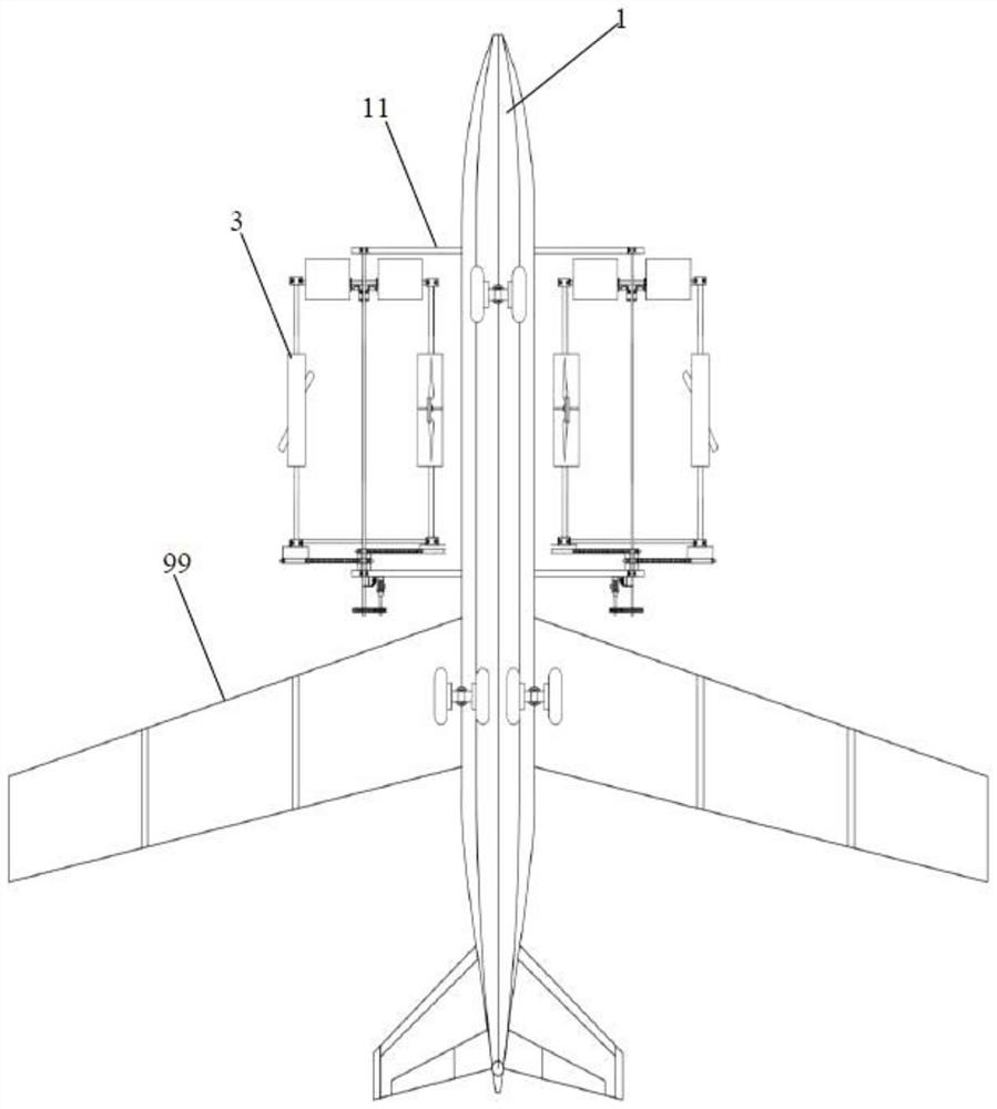
[0153] The embodiment of the present invention discloses a flapping rotor aircraft, comprising: a fuselage 1, a flapping rotor 3, a retractable upper wing, a landing gear, a jet engine and a controller, the jet engine is installed on the fuselage 1, and the landing gear Installed on the abdomen of the fuselage 1, the tail of the fuselage 1 is provided with an empennage or a tail rotor, and both sides of the fuselage are symmetrically fixed with flapping rotor brackets 11;

[0154] The flapping rotor 3 includes: a revolution main shaft 21, a revolution motor 22, a revolution transmission gear set 24, an autorotation transmission, an autorotation main shaft 23 and a rotor mechanism 30;

[0155] The revolving main shaft 21 is arranged on both sides of the fuselage 1 through the flapping rotor bracket 11, and is rotatably connected with the flapping rotor bracket 11 through a bearing, and its axial centerline is parallel to the axial centerline of the fuselage 1, while the revolvin...

Embodiment 2

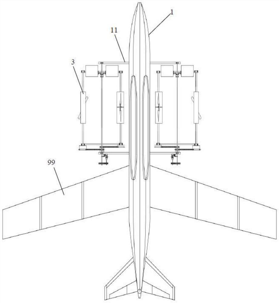
[0169] Embodiment 2 of the present invention is different from Embodiment 1 in that the controller of the present invention makes the folding wing 99 in the unfolded state by controlling the folding mechanism, and the jet engine works at the same time. Providing thrust and generating a pressure difference in the airflow through the unfolded folded wings to have a lift, and rising with the cooperation of the landing gear, can significantly increase the speed of ascent, and at the same time, the invention can have the advantage of fast sailing speed of a fixed-wing aircraft.

Embodiment 3

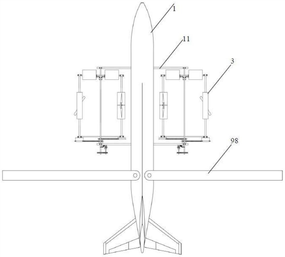
[0171] The difference from Embodiment 2 is that the retractable upper single wing is a fixed-axis rotary wing 98, the bottom end of the wing root of the fixed-axis rotary wing 98 is fixed with the wing shaft, and the wing drive motor is fixed in the fuselage 1, and the wing drive motor passes through the gear. The transmission mechanism is connected to the wing shaft to drive the fixed-axis rotary wing 98 to rotate, and the wing drive motor is electrically connected to the controller.

[0172] In the present invention, the fixed-axis rotary wing 98 is used as the retractable upper wing, not only the effect in Embodiment 1 can be realized, but also the fixed-axis rotary wing 98 can be rotated to be parallel to the axis of the fuselage 1, so that the contraction range is larger, thus reducing The space occupancy rate of the present invention and the resistance during flight make the efficiency of flight improved, and at the same time, since the fixed-axis rotary wing 98 of the pr...


PUM


Abstract

The invention discloses a flapping-like rotor aircraft, which is characterized in that revolution spindles of flapping rotors are arranged on the two sides of a fuselage through flapping rotor supports, meanwhile, a front rotating arm and a rear rotating arm are correspondingly and perpendicularly fixed to the head end and the tail end of each revolution spindle respectively, and autorotation spindles are rotationally connected with the front rotating arms and the rear rotating arms respectively and located on the two sides of the revolution spindles respectively; a revolution motor drives therevolution spindle to revolve for a circle through a revolution transmission gear set, the revolution spindle drives the autorotation spindle to autorotate for a half circle through an autorotation transmission device, retractable upper single wings are arranged on the two sides of the back of the fuselage respectively, the height difference between the retractable upper single wings and the flapping rotor support is greater than the sum of the heights of the front rotating arm and the rotor mechanism, and meanwhile, the controller is electrically connected with the retractable upper single wing and a jet engine to control the working states of the retractable upper single wing and the jet engine. The invention provides a flapping-like rotor aircraft which improves the ascending efficiency and the navigation speed.

Description

technical field [0001] The present invention relates to the field of aircraft technology, and more specifically relates to a flapping rotorcraft. Background technique [0002] The flapping rotorcraft is a novel aircraft imitating the flight of birds. It has the advantages of vertical lift-off and hovering in the air that rotorcraft and helicopters have. Part of the lift will cancel each other out, resulting in lower efficiency of the flapping rotorcraft rise, while the flapping rotorcraft in the prior art has poor stability in generating lift, resulting in lower safety, and the flapping rotorcraft in the prior art Only lift is provided by flapping the rotor, resulting in lower efficiency of its navigation. Contents of the invention [0003] The present invention aims to solve one of the above-mentioned technical problems in the prior art at least to a certain extent. [0004] In view of this, the invention provides a flapping rotorcraft, which improves the efficiency of ...

Claims


Application Information

Patent Timeline
Patent Type & Authority Applications(China)
IPC IPC(8): B64C27/22B64C27/32B64C25/02B64C25/34B64D27/16B64C33/02B64D27/24B64D35/02B64D35/00
CPCB64C27/22B64C27/32B64C25/02B64C25/34B64D27/16B64C33/02B64D27/24B64D35/02B64D35/00Y02T50/60
Inventor 王志成
Owner GUANGDONG GUOSHIJIAN TECH DEV CO LTD
Why Eureka
Try Eureka