Temporary barrier for environmental isolation

A kind of environmental isolation and temporary technology, applied in the direction of using liquid separation agent, filtration separation, separation method, etc., can solve the problems of poor noise reduction effect, affecting the quality of life of residents, affecting the working status of employees, etc., and achieve the effect of improving dust removal efficiency

Active Publication Date: 2021-02-26
JIUJIANG UNIVERSITY
View PDF7 Cites 1 Cited by
  • Summary
  • Abstract
  • Description
  • Claims
  • Application Information

AI Technical Summary

Problems solved by technology

[0002] During the construction and production process of the construction site, there will be a certain amount of noise, which will affect the working status of the employees, and also bring noise pollution to the surrounding residents, seriously affecting the quality of life of the residents. In order to improve the noise influencing factors, the installation on the site Various sound barrier panels were installed to reduce the impact of noise on residents
[0003] When the existing construction site barriers are in use, the noise reduction effect is poor, and they do not have the effect of automatic dust removal. When in use, the height cannot be automatically raised, which cannot meet the needs of use

Method used


Image

  • Temporary barrier for environmental isolation
  • Temporary barrier for environmental isolation
  • Temporary barrier for environmental isolation

Examples


Embodiment 1

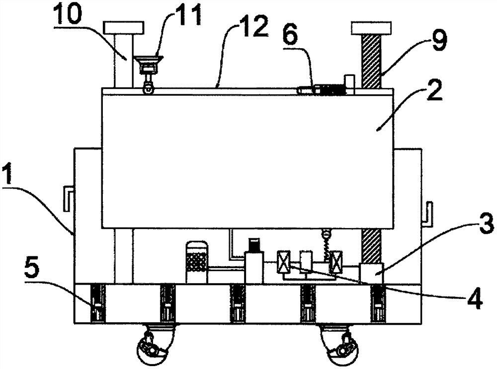
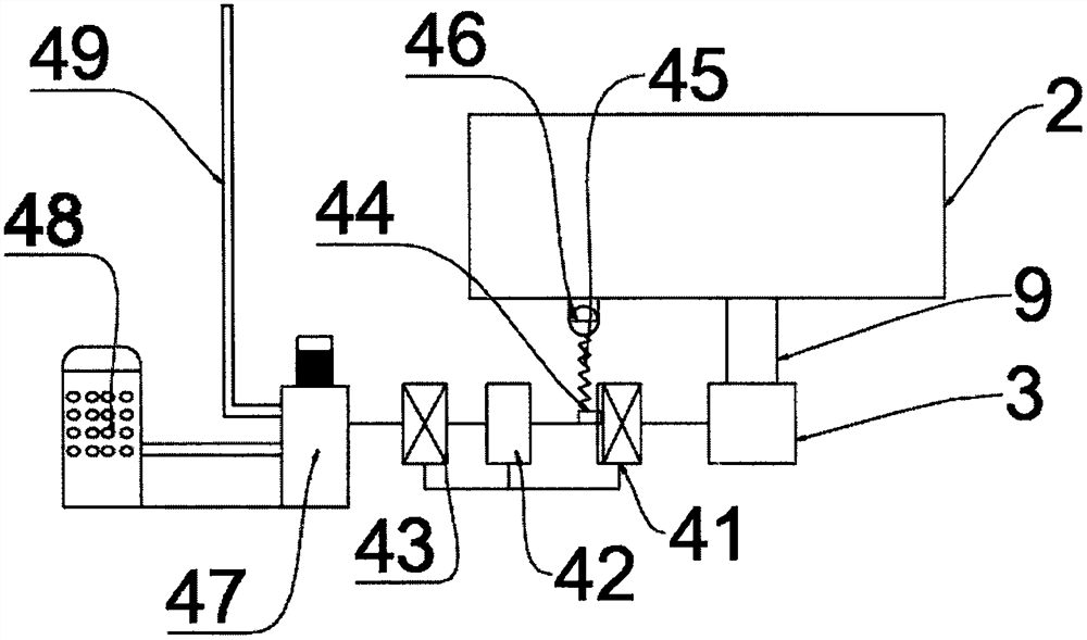
[0029] refer to Figure 1 to Figure 5, a temporary barrier for environmental isolation, including a support side plate 1 and a top plate 2 slidingly installed inside the support side plate 1, a motor 3 is fixedly installed on the inner bottom surface of the support side plate 1, and the output end of the motor 3 is connected with Screw rod 9, and screw rod 9 is threadedly connected with top plate 2, and the bottom of top plate 2 is provided with control device 4, and the side of top plate 2 away from screw rod 9 is slidably connected with the limit bar 10 that is fixedly installed on the inner bottom surface of support side plate 1, and The control device 4 includes an acoustic sensor 41, a power supply 42 and a second acoustic sensor 43 fixedly installed on the inner wall of the support side plate 1, and the power supply 42 is arranged in the middle of the acoustic sensor 41 and the second acoustic sensor 43, and the power supply 42 One side close to the acoustic sensor 41 is...

Embodiment 2

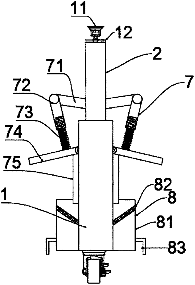
[0037] refer to Figure 6 , a temporary barrier for environmental isolation. Compared with Embodiment 1, the stabilizing device 5 in this embodiment includes a sleeve 51 fixedly installed on the inner top surface of the bottom plate and a slide rail 56 arranged inside the sleeve 51, and the sleeve A stabilizing spring 52 is fixedly installed on the inner top surface of the barrel 51 , a slider 53 slidingly connected with a slide rail 56 is connected below the stabilizing spring 52 , and a bottom bar 55 is connected to the side of the slider 53 away from the stabilizing spring 52 .

[0038] Working principle: When in use, the stability of the device is facilitated by setting the stabilizing device 5 to ensure stable operation during the construction process. When the device is impacted, the sleeve 51 moves down and drives the stabilizing spring 52 to compress, which is convenient for timely Shock offset.


PUM


Abstract

The invention discloses a temporary barrier for environmental isolation. The temporary barrier comprises a supporting side plate and a top plate slidably mounted in the supporting side plate, a motoris fixedly mounted on the inner bottom surface of the supporting side plate, the output end of the motor is connected with a screw, the screw is in threaded connection with the top plate, a control device is arranged below the top plate, and the side, away from the threaded rod, of the top plate is slidably connected with a limiting rod fixedly installed on the inner bottom face of the supportingside plate. When the temporary barrier is used, the temporary barrier is conveniently lifted or contracted in use by arranging the screw rod, dust removal and ascending noise reduction of the temporary barrier are facilitated in construction by arranging the control device, in construction, due to high noise, a sound-sensitive sensor is switched on, under connection of a power supply, the motor iselectrified to rotate, meanwhile, the screw rod is driven to rotate, then the top plate is driven to ascend, and when the top plate ascends, springs are driven to stretch.

Description

technical field [0001] The invention relates to the technical field of isolation barriers, in particular to a temporary barrier for environmental isolation. Background technique [0002] During the construction and production process of the construction site, there will be a certain amount of noise, which will affect the working status of the employees, and also bring noise pollution to the surrounding residents, seriously affecting the quality of life of the residents. In order to improve the noise influencing factors, the installation on the site Various sound barrier panels were installed to reduce the impact of noise on residents. [0003] When the existing construction site barriers are used, the noise reduction effect is poor, and they do not have the effect of automatic dust removal. When they are used, they cannot be automatically adjusted in height, which cannot meet the use requirements. Contents of the invention [0004] The purpose of the present invention is ...

Claims


Application Information

Patent Timeline
Patent Type & Authority Applications(China)
IPC IPC(8): E04H17/16E04H17/22E04H17/00H02K7/10H02K7/06B01D29/03B01D47/06
CPCE04H17/16E04H17/22E04H17/00H02K7/10H02K7/06B01D47/06B01D29/03
Inventor 杨闵敏
Owner JIUJIANG UNIVERSITY
Why Eureka
Try Eureka