
Tunneling device for coal mining and implementation method thereof

A coal mining and fixing plate technology, which is applied in the direction of earthwork drilling and cutting machinery, etc., can solve the problems of increased screw rod damage, dust raising, unfavorable working environment, etc., so as to reduce the probability of coal falling and suppress dust The effect of raising and speeding up the mining progress

Inactive Publication Date: 2021-02-26
新汶矿业集团设计研究院有限公司
View PDF4 Cites 0 Cited by
  • Summary
  • Abstract
  • Description
  • Claims
  • Application Information

AI Technical Summary

Problems solved by technology

[0004] 1. Existing tunneling devices for coal mining use screw rods to crush and mine coal. Because the screw rod itself does not have a buffer device, the direct impact force is easy to cause damage to the screw rod, increasing the probability of damage to the screw rod, and It is not conducive to the protection and replacement of the screw rod, and affects the mining progress;
[0005] 2. The existing tunneling device for coal mining can only transport coal, because the height of the conveying device cannot be adjusted, which increases the inconvenience of coal acceptance, and there is no baffle device, which increases the probability of coal falling;
[0006] 3. The existing tunneling device for coal mining does not have an enclosure device as a whole, which is likely to cause a large amount of dust to rise, which is not conducive to creating a good working environment

Method used


Image

  • Tunneling device for coal mining and implementation method thereof
  • Tunneling device for coal mining and implementation method thereof
  • Tunneling device for coal mining and implementation method thereof

Examples


Embodiment 1

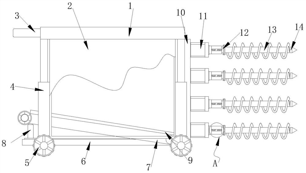
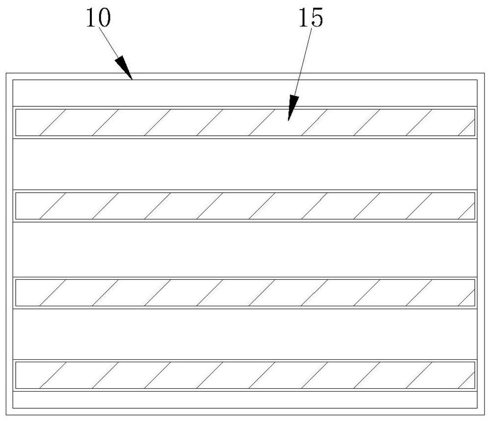
[0040] Such as figure 1 and figure 2 shown;

[0041] figure 1 It is a structural schematic diagram of the present invention;

[0042] figure 2 It is a side view of the fixing frame in the present invention;

[0043] A tunneling device for coal mining, comprising a fixed plate 1, hydraulic rods 4 are installed at the four corners of the bottom surface of the fixed plate 1, the telescopic shafts of the four hydraulic rods 4 are fixedly connected with the fixed plate 1, and are located on the fixed plate 1 A fixed frame 10 is installed between two symmetrical hydraulic rods 4 on the right side of the bottom surface, and a plurality of motors 11 are installed on the end face of the fixed frame 10. The output shaft of the motor 11 is fixedly connected with a screw rod 13, and four hydraulic rods 4 There is a conveying frame 7 between them, the bottom ends of the four hydraulic rods 4 are equipped with walking wheels 5, the front and back of the fixed plate 1 are equipped wit...


PUM


Abstract

The invention belongs to the technical field of coal mining, and particularly relates to a tunneling device for coal mining and an implementation method thereof. The tunneling device comprises a fixedplate; hydraulic rods are installed at four corners of the bottom face of the fixed plate correspondingly; telescopic shafts of the four hydraulic rods are fixedly connected with the fixed plate; anda fixed frame is installed between the two symmetrical hydraulic rods located at the front end and the rear end of the right side of the bottom face of the fixed plate. Due to the fact that a drill bit is in a pointed cone shape, the drill bit can be inserted into a coal seam conveniently, under cooperation of a second spring, the drill bit is buffered, the digging force of the drill bit is enhanced while the drill bit is protected, and the mining progress is accelerated; a fixed rod can slide in a through groove through the elastic effect of a third spring and a base plate, the fixed rod anda screw rod have buffering effects, direct impact on the screw rod is avoided, and protection of the screw rod is facilitated; and meanwhile, a sliding rod slides in a sliding groove and a connectinggroove, under the traction of two fourth springs, the elastic effect of the screw rod is enhanced again, and the buffering performance is enhanced.

Description

technical field [0001] The invention belongs to the technical field of coal mining, and in particular relates to a driving device for coal mining. Background technique [0002] Coal is an area where humans mine coal resources in coal-rich mining areas, which are generally divided into underground coal mines and open-pit coal mines. When the coal seam is far away from the surface, it is generally chosen to excavate coal in underground tunnels. This is an underground coal mine. When the distance between the coal seam and the surface is very close, it is generally selected to directly strip the surface soil layer to excavate coal. This is an open-pit coal mine. The tunneling device is One of the equipment for coal mining. [0003] There are following problems in existing technology: [0004] 1. Existing tunneling devices for coal mining use screw rods to crush and mine coal. Because the screw rod itself does not have a buffer device, the direct impact force is easy to cause d...

Claims


Application Information

Patent Timeline
Patent Type & Authority Applications(China)
IPC IPC(8): E21C27/22E21C35/00E21C35/20E21C35/22
CPCE21C27/22E21C35/00E21C35/20E21C35/22
Inventor 董凤宝田华张林冲孙杨张竞生李冉邢磊徐哲文张盛文
Owner 新汶矿业集团设计研究院有限公司
Learn More