
Transmission part control method and system of head shaking lamp

A control method and technology of machine parts, applied in transmission belts, energy-saving control technology, components of lighting devices, etc., can solve problems such as low positioning accuracy, different deformation displacements, and angular positioning deviations

Active Publication Date: 2021-02-26
GUANGZHOU YAJIANG PHOTOELECTRIC EQUIP CO LTD
View PDF6 Cites 0 Cited by
  • Summary
  • Abstract
  • Description
  • Claims
  • Application Information

AI Technical Summary

Problems solved by technology

The inventor found in the process of implementing the present invention that there are the following technical problems in the prior art: the synchronous belt itself is flexible, and the deformation and displacement caused by different pulling forces are different, which easily causes angular positioning deviation
Due to the low positioning accuracy of stepper motors used in stage moving head lamps, and the low requirements for optical code detection accuracy, the small angle offset caused by the elastic deformation of the synchronous belt is smaller than the effective range of optical code detection
The angle caused by the elastic deformation of the synchronous belt is projected through the optical long-distance. After the angle is multiplied, the projected light spot will have a significant position shift, which will affect the lighting design effect of the lighting engineer.

Method used


Image

  • Transmission part control method and system of head shaking lamp
  • Transmission part control method and system of head shaking lamp
  • Transmission part control method and system of head shaking lamp

Examples


Embodiment Construction

[0029] The following will clearly and completely describe the technical solutions in the embodiments of the present invention with reference to the accompanying drawings in the embodiments of the present invention. Obviously, the described embodiments are only some, not all, embodiments of the present invention. Based on the embodiments of the present invention, all other embodiments obtained by persons of ordinary skill in the art without creative efforts fall within the protection scope of the present invention.

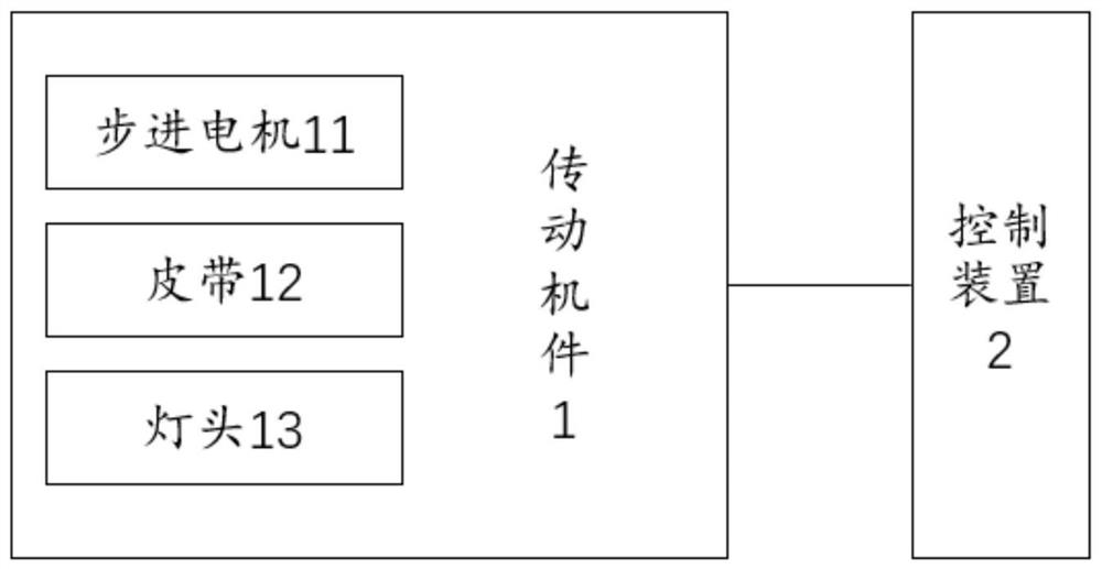
[0030] see figure 1 , is a structural schematic diagram of a transmission mechanism system of a moving head lamp provided by an embodiment of the present invention, including:

[0031] A transmission mechanism 1 and a control device 2 , wherein the transmission mechanism 1 includes a stepping motor 11 , a belt 12 and a lamp head 13 .

[0032] In this embodiment, the control device 2 is used to control the movement of the stepping motor 11, so that the stepping mot...


PUM


Abstract

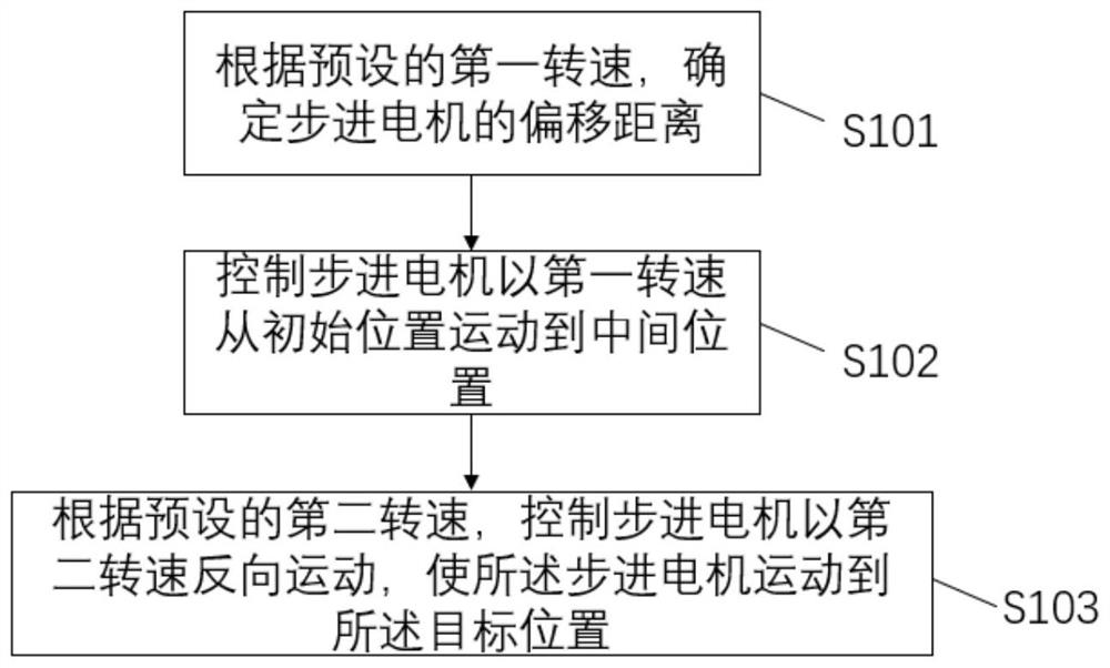
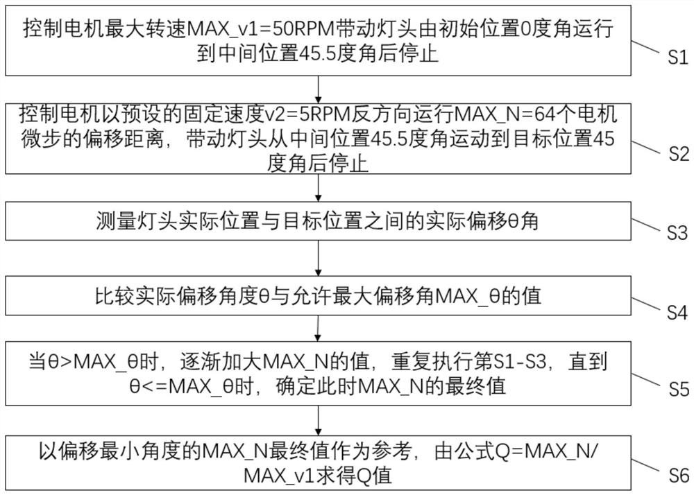
The invention discloses a transmission part control method and system for a head shaking lamp. The method comprises the steps of determining an offset distance of a stepping motor according to a preset first rotating speed, and controlling the stepping motor to move from an initial position to a middle position at the first rotating speed, wherein the step pitch stroke of the stepping motor from the initial position to the middle position is the sum of the target step pitch stroke and the offset distance, and the target step pitch stroke is the step pitch stroke of the stepping motor from theinitial position to a target position; and according to a preset second rotating speed, controlling the stepping motor to move reversely at the second rotating speed, and enabling the stepping motor to move to the target position from the middle position. By adopting the embodiment, angle deviation caused by elastic deformation of a belt can be reduced, and the positioning precision of the head shaking lamp is improved.

Description

technical field [0001] The invention relates to the field of stage lighting technology, in particular to a method and system for controlling a transmission mechanism of a moving head lamp. Background technique [0002] The lamp head transmission system of stage moving head lamps usually uses gears and synchronous belts as the transmission parts. It has the characteristics of simple and reliable structure, high transmission efficiency, convenient debugging, and low cost. It is widely used in the transmission system of stage moving head lamps. In the process of implementing the present invention, the inventors found that the following technical problems exist in the prior art: the timing belt itself has stretching elasticity, and the deformation and displacement caused by different pulling forces are different, which easily causes angle positioning deviation. Since the positioning accuracy of stepper motors used in stage moving head lamps is not high, and the requirements for ...

Claims


Application Information

Patent Timeline
Patent Type & Authority Applications(China)
IPC IPC(8): F21V14/02F21V23/00F16G1/06F21W131/406
CPCF21V14/02F21V23/003F16G1/06F21W2131/406Y02B20/40
Inventor 陈志曼黄荣丰陈运筹
Owner GUANGZHOU YAJIANG PHOTOELECTRIC EQUIP CO LTD
Learn More