
Low-angle-drift multi-band-pass optical filter

A band-pass filter, low-angle technology, applied in the field of filters, can solve the problem of not being able to provide low-angle offset filters, etc., to improve the recognition accuracy, reduce the angle offset, and improve the signal-to-noise ratio. Effect

Inactive Publication Date: 2020-01-31
FUZHOU PHOTOP QPTICS CO LTD
View PDF6 Cites 0 Cited by
  • Summary
  • Abstract
  • Description
  • Claims
  • Application Information

AI Technical Summary

Problems solved by technology

However, when applied to sensing and identification systems that operate on multiple wavelength bands simultaneously, this technology cannot provide filters that satisfy low angular shift characteristics

Method used


Image

  • Low-angle-drift multi-band-pass optical filter
  • Low-angle-drift multi-band-pass optical filter
  • Low-angle-drift multi-band-pass optical filter

Examples


Embodiment 1

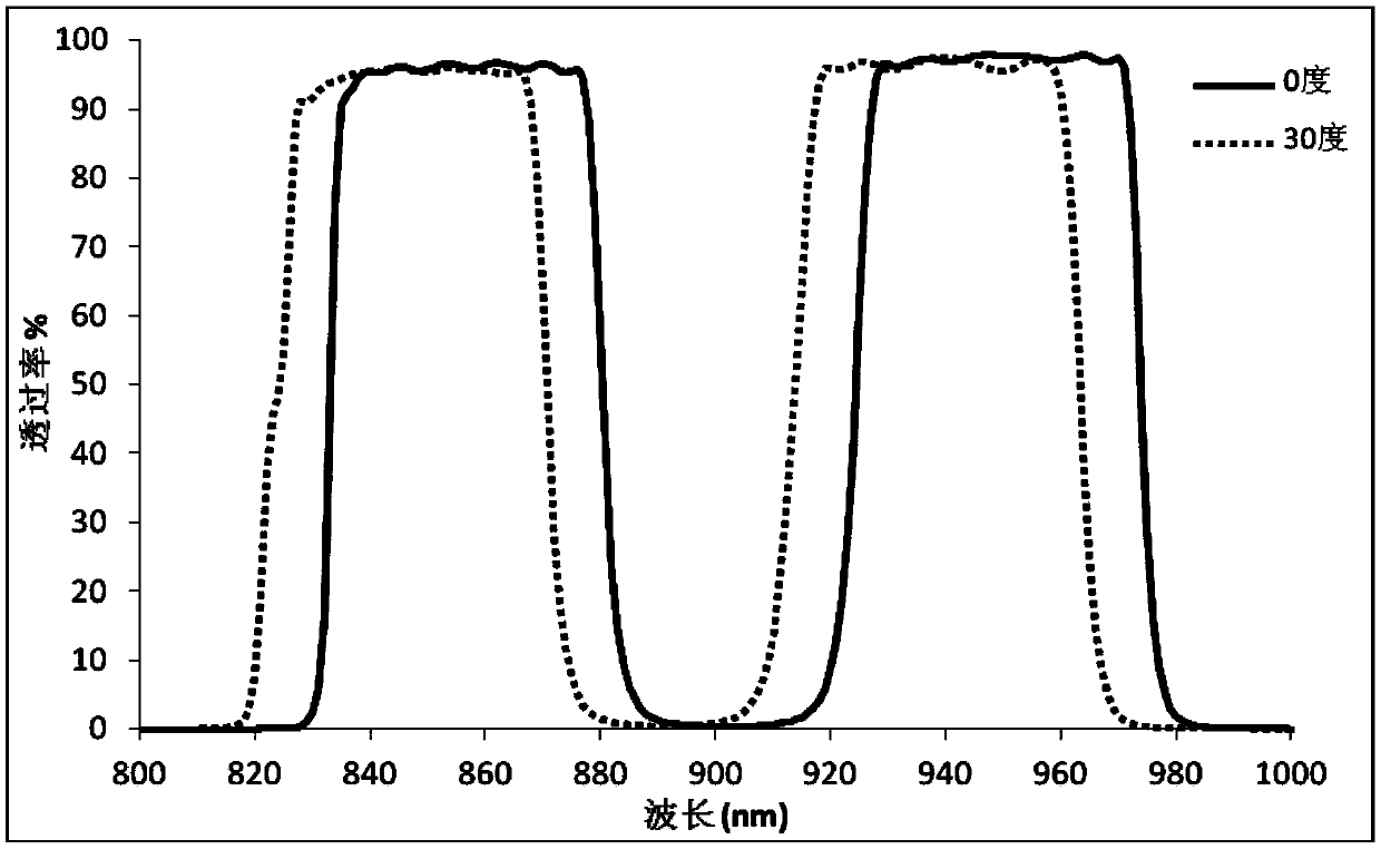
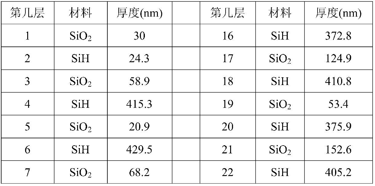
[0022] The transmission spectra of Example 1 at 0 degrees and 30 degrees incidence are in figure 2 Draw in. There are two passbands near 850nm and 940nm, which are referred to as passband 1 and passband 2 respectively hereinafter. As shown in Table 2, the wavelength of passband 1 is 836nm to 876nm, and the FWHM is 47nm; the wavelength of passband 2 is 928nm to 971nm, and the FWHM is 49.5nm; the two do not overlap. Within the pass band, the transmittance of the filter is greater than 90%; outside the pass band, the transmittance of the filter is lower than OD2 to achieve the purpose of filtering noise.

[0023] At an incident angle of 0 degrees, the center wavelength of pass band 1 is 856.8 nm, and the center wavelength of pass band 2 is 949.2 nm; at an incident angle of 30 degrees, the center wavelength of pass band 1 is 847.5 nm and the center wavelength of pass band 2 It is 938.6nm. Within the range of incident angles of 0 to 30 degrees, the center wavelength shifts of the t...


PUM

PropertyMeasurementUnit
wavelengthaaaaaaaaaa

Abstract

The invention discloses a low-angle-drift multi-band-pass optical filter. The low-angle-drift multi-band-pass optical filter comprises a substrate, a film system formed by alternately stacking a plurality of high-refractive-index film layers and a plurality of low-refractive-index film layers is arranged on the substrate, and the high-refractive-index film layers are made of SiH, SiOxHy or a mixture of SiH and SiOxHy. The refractive indexes of the high-refractive-index film layers are all larger than 3 within the wavelength range of 800-1600 nm. The multi-band-pass optical filter can be applied to a biological recognition system with multiple wavelengths applied at the same time, angle deviation is effectively reduced, the signal-to-noise ratio of an optical system is improved, and the recognition accuracy is improved.

Description

Technical field [0001] The present invention relates to the field of optical filters, in particular to a multi-bandpass optical filter with low angle drift. Background technique [0002] In the field of biometrics, a typical technical solution is to use infrared light to collect the characteristics of the identified creature. Use the light source to emit light in the infrared band, collect the return light through a sensor device such as CCD, analyze it by computer technology, build a 3D model (such as a face model) and extract features, so as to realize the identification and determination of identity features. [0003] In this sensing system, the optical filter is one of the most important components. The filter needs to have a sufficiently high transmittance for the working waveband, and at the same time, it needs to block the non-working waveband, especially the visible light waveband, to achieve the purpose of filtering noise. As the angle of incidence of light increases, th...

Claims


Application Information

Patent Timeline
Patent Type & Authority Applications(China)
IPC IPC(8): G02B5/20G02B5/28G06K9/00
CPCG02B5/207G02B5/281G02B5/285G06V40/20G02B5/20G02B5/28
Inventor 刘哲于光龙李昱苏炎林志强
Owner FUZHOU PHOTOP QPTICS CO LTD
Learn More