Drying upender for feed processing

A feed processing and turning machine technology, used in dryers, drying, non-progressive dryers, etc., can solve problems such as hidden dangers and high safety of hanging baskets, and achieve easy cleaning, improve drying efficiency, and improve shaking efficiency. Effect

Pending Publication Date: 2021-02-26
许文祥
View PDF29 Cites 0 Cited by
  • Summary
  • Abstract
  • Description
  • Claims
  • Application Information

AI Technical Summary

Problems solved by technology

[0005] The purpose of the present invention is to solve the problem that the hanging basket in the prior art has a large potential safety hazard during use, and proposes a drying and turning machine for feed processing

Method used


Image

  • Drying upender for feed processing
  • Drying upender for feed processing
  • Drying upender for feed processing

Examples


Embodiment 1

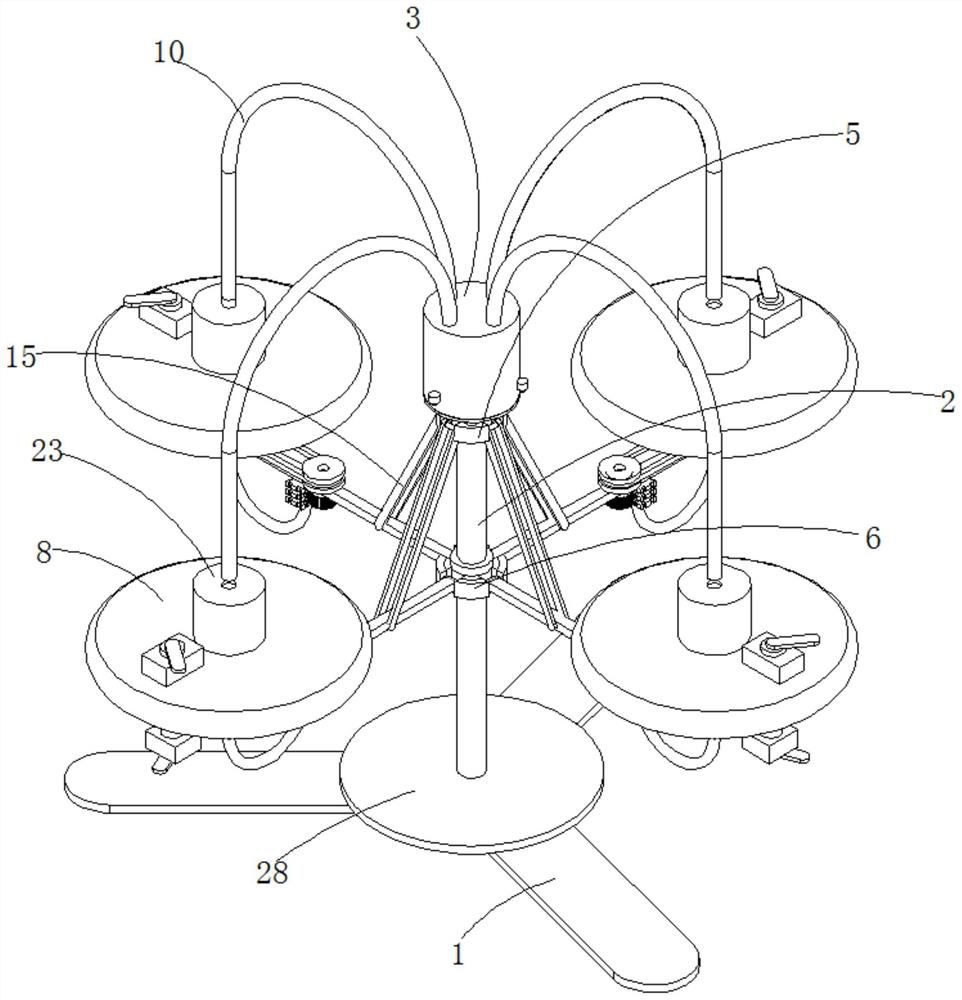
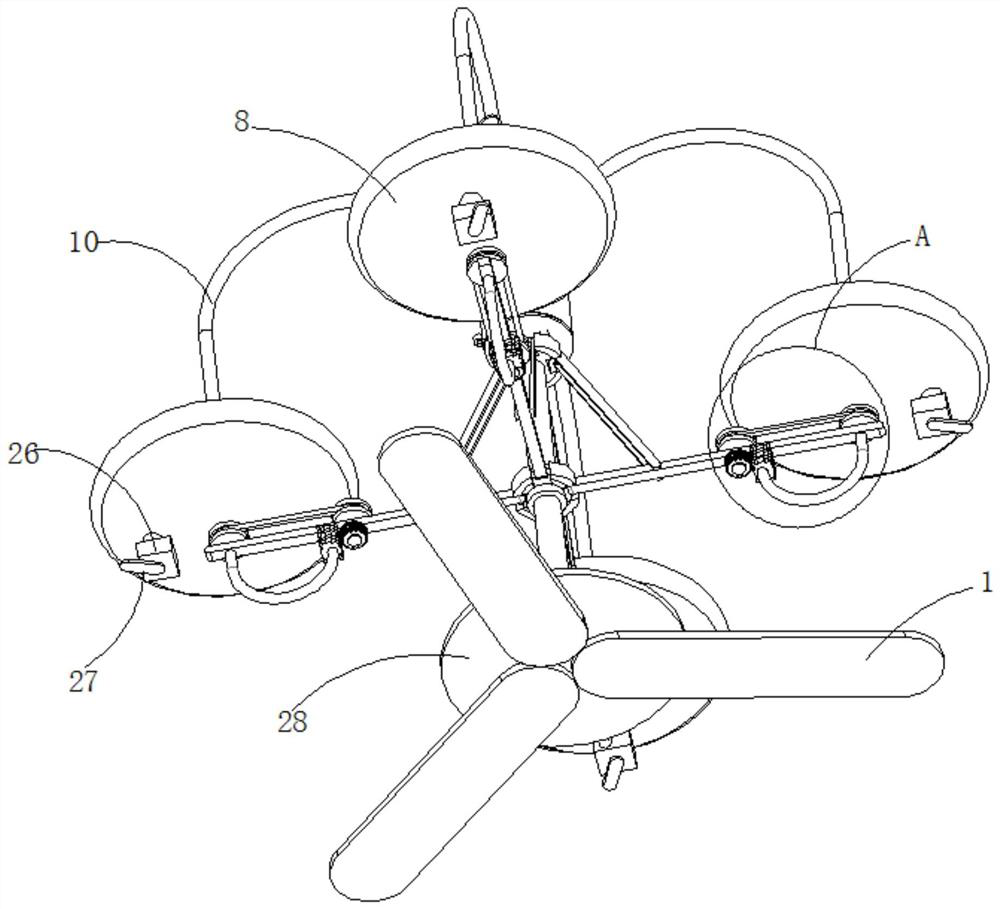
[0031] refer to Figure 1-6, a drying and turning machine for feed processing, comprising a fixed frame 1, a vertically arranged fixed rod 2 is affixed to the center of the top of the fixed frame 1, and an air cylinder 3 is affixed to the end of the fixed rod 2 away from the fixed frame 1. 3 The outer wall near the top of the fixed rod 2 is provided with evenly distributed pressure relief valves 4, the outer wall of the fixed rod 2 is connected with the upper sliding seat 5 and the lower fixed seat 6 in sequence along the vertical direction, and the upper sliding seat 5 is slidably connected to the fixed rod 2 The outer wall of the lower fixed seat 6 is fixedly connected to the middle section of the fixed rod 2, and the outer edge of the lower fixed seat 6 is rotatably connected with an evenly distributed mounting plate 7, and the end of the mounting plate 7 away from the lower fixed seat 6 is provided with a rotating assembly. The rotating end of the feed drying bucket 8 is f...

Embodiment 2

[0043] refer to Figure 1-6 , a drying and turning machine for feed processing, comprising a fixed frame 1, a vertically arranged fixed rod 2 is affixed to the center of the top of the fixed frame 1, and an air cylinder 3 is affixed to the end of the fixed rod 2 away from the fixed frame 1. 3 The outer wall near the top of the fixed rod 2 is provided with evenly distributed pressure relief valves 4, the outer wall of the fixed rod 2 is connected with the upper sliding seat 5 and the lower fixed seat 6 in sequence along the vertical direction, and the upper sliding seat 5 is slidably connected to the fixed rod 2 The outer wall of the lower fixed seat 6 is fixedly connected to the middle section of the fixed rod 2, and the outer edge of the lower fixed seat 6 is rotatably connected with an evenly distributed mounting plate 7, and the end of the mounting plate 7 away from the lower fixed seat 6 is provided with a rotating assembly. The rotating end of the feed drying bucket 8 is ...


PUM


Abstract

The invention discloses a drying upender for feed processing, and belongs to the technical field of feed processing. The drying upender for feed processing comprises a fixing frame, a vertically-arranged fixing rod is fixedly connected to the center of the top of the fixing frame, an air cylinder is fixedly connected to one end, away from the fixing frame, of the fixing rod, pressure relief valvesare uniformly distributed on an outer wall, close to the top end of the fixing rod, of the air cylinder, an upper sliding base and a lower fixing base are connected to the outer wall of the fixing rod in sequence in the vertical direction, the upper sliding base is slidably connected to the outer wall of the fixing rod, the lower fixing base is fixedly connected to the middle section of the fixing rod, the outer edge of the lower fixing base is rotatably connected with uniformly-distributed mounting plates, rotating assemblies are arranged at one ends, away from the lower fixing base, of themounting plates, rotating ends of the rotating assemblies are fixedly connected with feed drying hoppers, heating coils are fixedly connected to inner walls of the tops of the feed drying hoppers, andan intercepting assembly is further fixedly connected to the center of the top of each feed drying hopper. According to the drying upender, through wind stirring, the contact efficiency of hot air and feed is improved, and then the drying efficiency of the feed is improved.

Description

technical field [0001] The invention relates to the technical field of feed processing, in particular to a drying and turning machine for feed processing. Background technique [0002] Feed is the general term for the food of animals raised by all people. In a narrower sense, general feed mainly refers to the food of animals raised in agriculture or animal husbandry. The feed includes soybean, soybean meal, corn, fish meal, amino acid, miscellaneous meal, whey powder, oil, meat and bone meal, grains, feed additives and more than ten varieties of feed materials. Feed needs to be dried during the processing process to remove excess water in the feed. In the prior art, the feed is usually dried by hot air drying. In this way, the feed is piled up, and the drying of the feed is not ideal. [0003] In the prior art, the invention patent with the patent application number CN201921212766.0 discloses "a feed processing turning and drying device, including a drying box, a base insta...

Claims


Application Information

Patent Timeline
IPC IPC(8): F26B11/18F26B21/00F26B25/02F26B25/04F26B25/00F26B25/18
CPCF26B11/18F26B21/001F26B25/02F26B25/04F26B25/00F26B25/18
Inventor 许文祥
Owner 许文祥
Why Eureka
Try Eureka