Voltage detection circuit and electronic equipment

A technology of voltage detection circuit and voltage regulation circuit, applied in the direction of measuring current/voltage, measuring device, measuring electric variable, etc., can solve the problem of output voltage drop, unable to replace or charge the battery in time, unable to know the size of the battery voltage, etc. Achieve the effect of reducing cost, simplifying structure and testing process

Active Publication Date: 2022-04-22
HISENSE VISUAL TECH CO LTD
View PDF8 Cites 0 Cited by
  • Summary
  • Abstract
  • Description
  • Claims
  • Application Information

AI Technical Summary

Problems solved by technology

For batteries, as the use time increases, its power will decrease, which will also lead to a decrease in its output voltage, and when the output voltage of the battery is lower than a certain value, it can no longer continue to serve electronic equipment normal power supply
[0003] At present, in order to realize the detection of the battery voltage, it is usually necessary to configure a special voltage detection sensor in the electronic device, or configure a special voltage detection chip to realize it, which requires a high cost
[0004] For some cheap electronic devices, such as infrared remote controllers, children's toys, electronic watches, etc., due to cost considerations, there is usually no function of detecting battery voltage, so that users cannot know the battery voltage when using such electronic devices. voltage, so that the battery cannot be replaced or charged in time, which affects the user's use

Method used


Image

  • Voltage detection circuit and electronic equipment
  • Voltage detection circuit and electronic equipment
  • Voltage detection circuit and electronic equipment

Examples


Embodiment Construction

[0040] In order to make the purpose, technical solutions and advantages of the embodiments of the present application clearer, the technical solutions in the embodiments of the present application will be clearly and completely described below in conjunction with the drawings in the embodiments of the present application. Obviously, the described embodiments It is only a part of the embodiments of the present application, but not all the embodiments. Based on the embodiments in this application, all other embodiments obtained by persons of ordinary skill in the art without making creative efforts belong to the scope of protection of this application.

[0041] The terms "first", "second" and the like in the specification, claims and drawings of the present application are used to distinguish similar objects, and not necessarily used to describe a specific sequence or sequence.

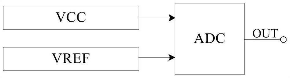
[0042] At present, in order to realize the detection of the battery voltage, it is usually necessary...


PUM


Abstract

Embodiments of the present application provide a voltage detection circuit and electronic equipment. The voltage detection circuit only includes a first voltage regulation circuit, a second voltage regulation circuit, a subtractor, a comparator, and a controller, wherein the first voltage regulation circuit is connected in series to The voltage source to be measured is connected to the first end of the comparator; the second voltage regulation circuit is connected in series to the voltage source to be measured and the first input end of the subtractor; the second input end of the subtractor is connected to the voltage source to be measured, and the subtraction The output terminal of the comparator is connected with the second terminal of the comparator; when detecting the voltage of the voltage source to be measured, the controller first adjusts the output voltage of the second voltage regulating circuit to the first voltage, and then continuously adjusts the output voltage of the first voltage regulating circuit output voltage until the output level of the comparator is switched, and then the voltage value of the voltage source to be tested can be determined according to the output voltage of the first voltage regulating circuit before and after the switching of the output level of the comparator and the above-mentioned first voltage range at a lower cost.

Description

technical field [0001] The embodiments of the present application relate to the technical field of voltage detection, and in particular to a voltage detection circuit and electronic equipment. Background technique [0002] In daily life, many electronic devices are powered by built-in batteries for the convenience of users. For batteries, as the use time increases, its power will decrease, which will also lead to a decrease in its output voltage, and when the output voltage of the battery is lower than a certain value, it can no longer continue to serve electronic equipment Perform normal power supply. [0003] At present, in order to realize the detection of the battery voltage, it is usually necessary to configure a special voltage detection sensor in the electronic device, or configure a special voltage detection chip to realize it, which requires high cost. [0004] For some cheap electronic devices, such as infrared remote controllers, children's toys, electronic watc...

Claims


Application Information

Patent Timeline
Patent Type & Authority Patents(China)
IPC IPC(8): G01R19/165
CPCG01R19/16595
Inventor 王守帅沈润渊刘云龙
Owner HISENSE VISUAL TECH CO LTD
Why Eureka
Try Eureka