Insulating plate and battery module

A battery module and insulating plate technology, applied in battery pack parts, battery caps/end caps, circuits, etc., can solve the problems of poor connection strength, poor reliability, difficult operation, etc., to simplify the structure and improve the efficiency of the group , the effect of reliable connection

Pending Publication Date: 2021-02-26
HUBEI JINQUAN NEW MATERIALS CO LTD
View PDF0 Cites 1 Cited by
  • Summary
  • Abstract
  • Description
  • Claims
  • Application Information

AI Technical Summary

Problems solved by technology

[0002] The battery module is usually equipped with a blister cover and a blister isolation plate. During assembly, there is no good solution for fixing the blister cover and the blister isolation plate. The existing blister cover and the blister isolation The board is fixed by sticking double-sided adhesive or sticking structural adhesive between the blister cover and the blister insulation board. This fixing method has the following disadvantages: the double-sided adhesive has poor bonding strength, and the Easy to fail; sticking with double-sided adhesive, easy to age; the adhesive structure is difficult to operate, the amount of glue and the bonding position are difficult to control; the adhesive structure makes battery module maintenance difficult, and once the upper cover is opened, the battery module structure will be destroyed
[0003] Therefore, there is an urgent need for an insulating board to solve the above problems such as difficult operation, poor connection strength and poor reliability.

Method used


Image

  • Insulating plate and battery module
  • Insulating plate and battery module
  • Insulating plate and battery module

Examples


Embodiment Construction

[0029] In order to make the technical problems solved by the present invention, the technical solutions adopted and the technical effects achieved clearer, the technical solutions of the embodiments of the present invention will be further described in detail below in conjunction with the accompanying drawings. Obviously, the described embodiments are only the technical solutions of the present invention. Some, but not all, embodiments. Based on the embodiments of the present invention, all other embodiments obtained by those skilled in the art without creative efforts fall within the protection scope of the present invention.

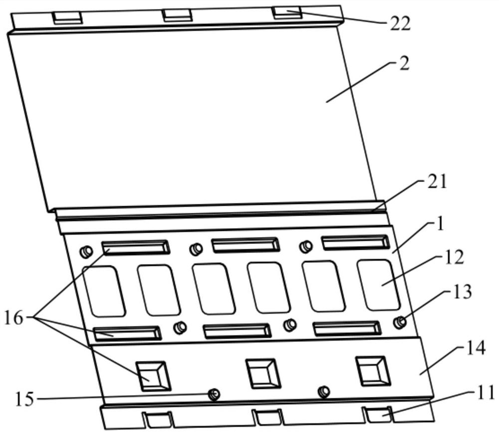
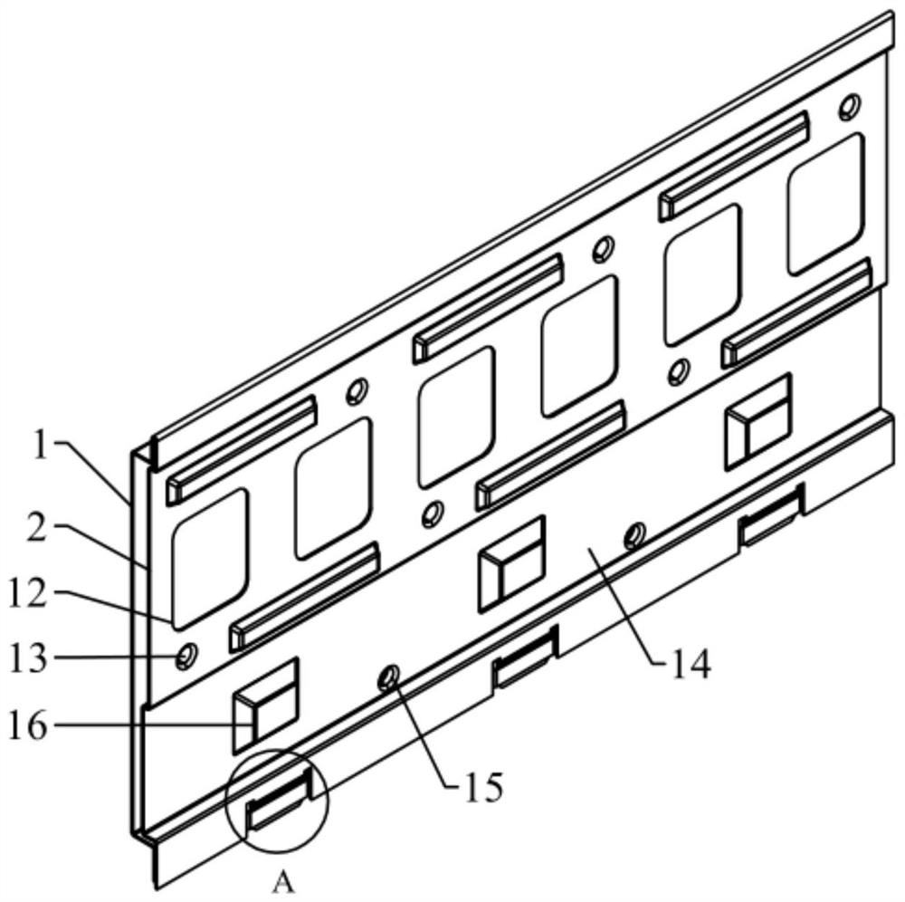
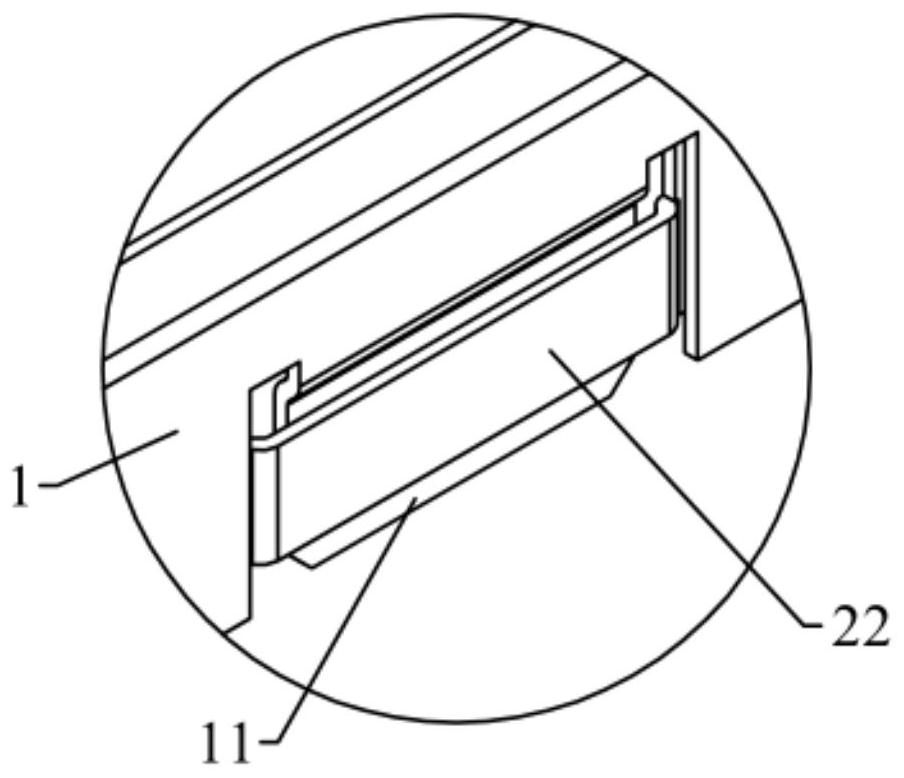
[0030] Such as Figure 1-Figure 4 As shown, this embodiment provides an insulating plate for a battery module, the insulating plate includes a bottom plate 1 and a cover plate 2, the bottom plate 1 is arranged at one end of the cell 100 of the battery module; the cover plate 2 is integrated with the bottom plate 1 It is provided that a crease 21 is pr...


PUM


Abstract

The invention relates to the technical field of battery modules, and discloses an insulating plate and a battery module. The insulating plate comprises a bottom plate and a cover plate, and the bottomplate is arranged at one end of a battery cell of the battery module; the cover plate and the bottom plate are integrally arranged, a crease is arranged at the joint of the cover plate and the bottomplate, and the cover plate can be folded relative to the bottom plate along the crease and buckled on the bottom plate. The bottom plate and the cover plate are arranged into a whole, the cover plateis arranged to be buckled with the bottom plate through folding, the bottom plate and the cover plate do not need to be connected and fixed together through additional parts, the structure is simplified, the grouping efficiency is improved, the problems of degumming, aging and abnormal sound caused by a gap between the bottom plate and the cover plate are solved. And meanwhile, compared with a bonding connection mode in the prior art, the connection mode that the bottom plate and the cover plate are arranged into a whole is more reliable.

Description

technical field [0001] The invention relates to the technical field of battery modules, in particular to an insulating plate and a battery module. Background technique [0002] The battery module is usually equipped with a blister cover and a blister isolation plate. During assembly, there is no good solution for fixing the blister cover and the blister isolation plate. The existing blister cover and the blister isolation The board is fixed by sticking double-sided adhesive or sticking structural adhesive between the blister cover and the blister insulation board. This fixing method has the following disadvantages: the double-sided adhesive has poor bonding strength, and the It is easy to fail; it is easy to age due to double-sided adhesive bonding; the adhesive structure is difficult to operate, and the amount of glue and the bonding position are difficult to control; the adhesive structure makes it difficult to maintain the battery module, and once the upper cover is opene...

Claims


Application Information

Patent Timeline
Patent Type & Authority Applications(China)
IPC IPC(8): H01M50/204H01M50/244H01M50/258H01M50/264H01M50/271H01M50/287
CPCY02E60/10
Inventor 胡磊
Owner HUBEI JINQUAN NEW MATERIALS CO LTD
Why Eureka
Try Eureka