
Semiconductor current control mechanism for new energy photovoltaic power generation and energy storage

A photovoltaic power generation and semiconductor technology, which is applied in the field of semiconductor flow control mechanisms for new energy photovoltaic power generation and energy storage, can solve problems such as low economic benefits, no energy storage function, and users cannot control how to use electricity or sell electricity to the grid. , to achieve the effect of increasing economic benefits

Inactive Publication Date: 2021-02-26
蓝迟高
View PDF0 Cites 1 Cited by
  • Summary
  • Abstract
  • Description
  • Claims
  • Application Information

AI Technical Summary

Problems solved by technology

[0005] Aiming at the deficiencies of the prior art, the present invention provides a semiconductor current control mechanism for new energy photovoltaic power generation and energy storage, which has the functions of photovoltaic power generation and energy storage at night, and users can control how to use or sell electricity at any time Power to the grid, greatly improving economic benefits, energy saving and environmental protection, etc., solves the problem that ordinary photovoltaic power generation equipment cannot perform photovoltaic power generation at night, does not have the function of energy storage, and users cannot control how to use electricity or sell electricity to the grid. Low benefit, inability to save energy and protect the environment

Method used


Image

  • Semiconductor current control mechanism for new energy photovoltaic power generation and energy storage
  • Semiconductor current control mechanism for new energy photovoltaic power generation and energy storage
  • Semiconductor current control mechanism for new energy photovoltaic power generation and energy storage

Examples


Embodiment Construction

[0024] The following will clearly and completely describe the technical solutions in the embodiments of the present invention with reference to the accompanying drawings in the embodiments of the present invention. Obviously, the described embodiments are only some, not all, embodiments of the present invention. Based on the embodiments of the present invention, all other embodiments obtained by persons of ordinary skill in the art without making creative efforts belong to the protection scope of the present invention.

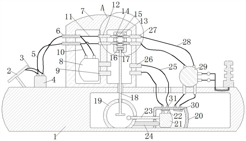
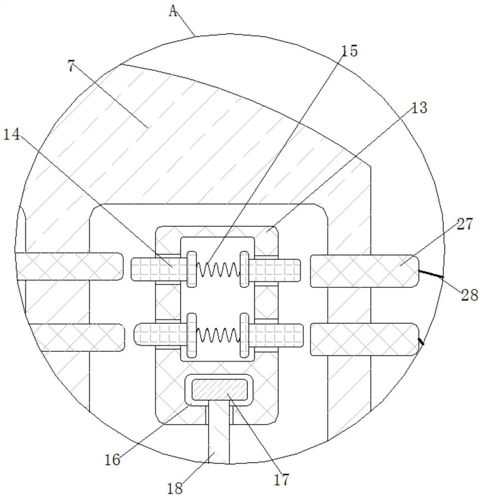
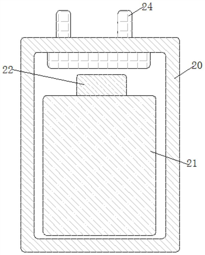
[0025] see Figure 1-4 , a semiconductor current control mechanism for new energy photovoltaic power generation and energy storage, including a bottom plate 1, the upper end of the bottom plate 1 is fixedly connected to the left side with a solar energy 2, and the solar energy 2 is set as a "two-stage type", wherein the upper section is a slope inclined to the left , the lower end is a tie rod inclined to the right. The solar energy 2 can be used for collectin...


PUM


Abstract

The invention relates to the technical field of semiconductor current control, and discloses a semiconductor current control mechanism for new energy photovoltaic power generation and energy storage.The mechanism comprises a bottom plate, solar power is fixedly connected to the left of the upper end of the bottom plate, a wire I is fixedly connected to the right end of the solar power, and an inverter is fixedly connected to the upper end of the bottom plate and located on the right of the solar power. A box is fixedly connected to the middle of the upper end of the bottom plate. Absorbed energy is converted into electric energy through solar power, the electric energy is transmitted into an inverter through the wire I to be processed, the inverter transmits the electric energy into a conductive block I through a wire II, the conductive block I guides the electric energy into an energy storage part through a wire III to be stored, and meanwhile the conductive block I transmits the electric energy into a telescopic block through a wire IV. The telescopic block transmits the electric energy to the conductive block IV through a spring, the conductive block IV transmits the electric energy to a power station through the wire VI to be used by a power station, and therefore the effects of saving energy, protecting the environment, greatly improving economic benefits and having the energy storage function are achieved.

Description

technical field [0001] The invention relates to the technical field of semiconductor flow control, in particular to a semiconductor flow control mechanism for new energy photovoltaic power generation and energy storage. Background technique [0002] Semiconductors have five major characteristics, namely resistivity characteristics, conductivity characteristics, photoelectric characteristics, negative resistivity temperature characteristics, and rectification characteristics. In today's photovoltaic power generation components, the principle of semiconductor current control is used more and more. By using semiconductor The thyristor, triode, field effect, etc. in the device constitute a control circuit to adjust the change of current in the circuit. [0003] With the installation of household photovoltaic power generation systems, how to effectively expand the use of photovoltaic power generation and improve power generation efficiency is a major challenge. In the existing ph...

Claims


Application Information

Patent Timeline
Patent Type & Authority Applications(China)
IPC IPC(8): H02S10/00H02S10/20H02S40/30
CPCH02S10/00H02S10/20H02S40/30Y02E10/50Y02E70/30
Inventor 蓝迟高
Owner 蓝迟高
Learn More