Joint frequency offset estimation method and system

A frequency offset estimation and frequency offset technology, applied in the field of frequency offset estimation, can solve the problem of structure and performance to be improved, and achieve the effect of improving performance and throughput rate, improving accuracy, and reasonable process structure

Active Publication Date: 2021-02-26
上海微波技术研究所(中国电子科技集团公司第五十研究所)
View PDF10 Cites 3 Cited by
  • Summary
  • Abstract
  • Description
  • Claims
  • Application Information

AI Technical Summary

Problems solved by technology

The structure and performance of this patent still have room for improvement

Method used


Image

  • Joint frequency offset estimation method and system
  • Joint frequency offset estimation method and system
  • Joint frequency offset estimation method and system

Examples


Embodiment Construction

[0066] The present invention will be described in detail below in conjunction with specific embodiments. The following examples will help those skilled in the art to further understand the present invention, but do not limit the present invention in any form. It should be noted that those skilled in the art can make several changes and improvements without departing from the concept of the present invention. These all belong to the protection scope of the present invention.

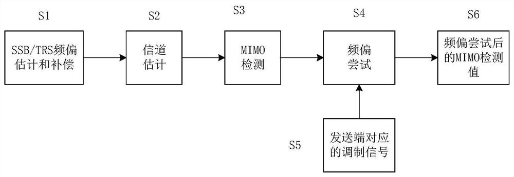
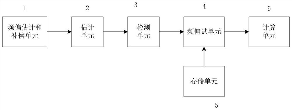
[0067] A joint frequency offset estimation method includes:

[0068] Step 1: Compensating for the estimated value of frequency offset using SSB or TRS;

[0069] Step 2: Execute the channel estimation module after the compensated signal has been processed in the middle;

[0070] Step 3: Execute the MIMO detection module for the channel estimated result;

[0071] Step 4: The process performs a frequency offset attempt on the result after MIMO detection;

[0072] Step 5: This process is the stored signa...


PUM


Abstract

The invention provides a joint frequency offset estimation method and a joint frequency offset estimation system. The joint frequency offset estimation method comprises the following steps: S1, compensating a frequency offset estimation value using SSB or TRS; S2, after the compensated signal is subjected to intermediate processing, a channel estimation module being executed; S3, executing an MIMOdetection module on a result after channel estimation; S4, performing frequency offset attempt on a result after MIMO detection; S5, storing the signals modulated by the sending end, and taking the stored signals modulated by the sending end as entry data of a frequency offset attempt module; and S6, acquiring the MIMO detection signal after frequency offset adjustment. The SSB and TRS referencesignals are periodic reference signals, a certain error exists in frequency offset estimation, frequency offset attempt is introduced into the detection module to perform joint frequency offset estimation, and the precision of frequency offset estimation is further improved.

Description

technical field [0001] The present invention relates to the technical field of frequency offset estimation, in particular to a joint frequency offset estimation method and system. Background technique [0002] For wireless communication systems, due to the time-varying nature of the wireless channel, the Doppler frequency shift of the wireless signal during transmission, or the frequency deviation between the carrier frequency of the transmitter and the local oscillator of the receiver, will destroy the communication between OFDM systems. Orthogonality, which in turn leads to mutual interference between subcarriers, deteriorating system performance. In severe cases, it will cause the entire receiver to be paralyzed, and the network will be disconnected. Therefore, before signal detection, it is necessary to estimate the carrier frequency offset, and then perform corresponding correction and compensation at the receiving end to ensure receiver performance. [0003] In the 5...

Claims


Application Information

Patent Timeline
Patent Type & Authority Applications(China)
IPC IPC(8): H04L27/38H04L27/26H04B7/0413H04B7/08
CPCH04L27/3854H04L27/2659H04L27/266H04L27/2695H04B7/0413H04B7/0854
Inventor 黄静静
Owner 上海微波技术研究所(中国电子科技集团公司第五十研究所)
Why Eureka
Try Eureka