Power system intelligent monitoring device and monitoring method thereof

An intelligent monitoring and power system technology, applied in the direction of using electrical devices, measuring devices, electrical components, etc., can solve problems such as internal structure damage, instantaneous temperature rise of power equipment, long time from finding problems to solving problems, etc.

Active Publication Date: 2021-02-26
CHINA SOUTHERN POWER GRID COMPANY
View PDF13 Cites 4 Cited by
  • Summary
  • Abstract
  • Description
  • Claims
  • Application Information

AI Technical Summary

Problems solved by technology

[0003] The existing power system contains a lot of power equipment, and when any ordinary power equipment operates independently, a short circuit may occur, causing the temperature of the power equipment to rise instantaneously, and if the temperature of the power equipment reaches a certain value, it will cause other damage The damage of the internal structure, while the traditional power equipment monitoring system is monitored by the electronic system. When a problem is found, the maintenance operator will move to the location where the failure occurred and repair it. For large-scale power systems, multiple maintenance personnel are required Real-time monitoring, and the time from finding the problem to solving the problem is usually long, which may cause damage to the power system

Method used


Image

  • Power system intelligent monitoring device and monitoring method thereof
  • Power system intelligent monitoring device and monitoring method thereof
  • Power system intelligent monitoring device and monitoring method thereof

Examples


Embodiment Construction

[0025]The following examples are for illustrative purposes only, and are not intended to limit the scope of the present invention.

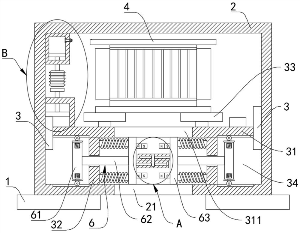
[0026]Such asFigure 1-4 As shown, an intelligent monitoring device for a power system includes a base 1. The base 1 is a two-part type, which are respectively arranged at the bottom ends of the left and right sides of the device casing 2. The upper surface of the base 1 is fixedly connected with the device casing 2. The wall surfaces on the left and right sides of the inner middle of the device housing 2 are fixedly connected with a thermally conductive block 3, a part of the upper end of the thermally conductive block 3 on the left is located inside the second evaporating liquid chamber 36, and the outer surfaces of the thermally conductive block 3 are fixedly connected to each other. There is a connecting plate 31, the middle of the connecting plate 31 is provided with a through hole 311, the structure of the through hole 311 is a circular structure, an...


PUM


Abstract

The invention belongs to the field of power device monitoring, and relates to a power system intelligent monitoring device. The device comprises a base, a device shell is fixedly connected to the surface of the upper end of the base, heat conduction blocks are fixedly connected to the wall faces of the left side and the right side of the middle of the interior of the device shell; a connecting plate is fixedly connected between the outer side surfaces of the heat conduction blocks; a fixing plate is fixedly connected to the lower end of the connecting plate; the lower end of the fixing plate is fixedly connected to the bottom face of the device shell; a supporting base is fixedly connected to the upper end of the connecting plate; and power equipment is fixedly connected to the upper end of the supporting base. Through a first evaporation cavity and a second evaporation cavity, a push-pull piece or a trigger rod is driven to move according to the principle that different evaporation liquids in the first evaporation cavity and the second evaporation cavity are heated and expanded at different temperatures; a ventilation effect on the device shell or a heat absorption and cooling effect is achieved by spraying cooling liquid through the push-pull piece or the trigger rod.

Description

Technical field[0001]The invention belongs to the field of power device monitoring, and in particular relates to a power system intelligent monitoring device and a monitoring method thereof.Background technique[0002]The main structure of the power system includes power sources (hydropower plants, thermal power plants, nuclear power plants, etc.), substations (boost substations, load center substations, etc.), transmission, distribution lines, and load centers. Interconnect to realize the exchange and adjustment of electric energy between different regions, thereby improving the safety and economy of power supply.[0003]The existing power system contains many power equipment, and when any kind of ordinary power equipment is operating independently, it is possible to short-circuit and cause the temperature of the power equipment to rise instantaneously. When the temperature of the power equipment reaches a certain value, if it is not handled in time, it will cause it. The internal stru...

Claims


Application Information

Patent Timeline
Patent Type & Authority Applications(China)
IPC IPC(8): H05K5/02H05K7/20G01K7/18G01K11/04
CPCH05K5/0213H05K7/20127H05K7/20345H05K7/20281H05K7/20381G01K7/18G01K11/04
Inventor 黄方能周剑梅勇
Owner CHINA SOUTHERN POWER GRID COMPANY
Why Eureka
Try Eureka