Power battery module structure for locomotive

A technology of power battery and module structure, applied in the direction of batteries, secondary batteries, structural parts, etc., can solve the problems of lack of safety protection measures in the power battery system, inability to know potential safety hazards in time, complicated production and assembly processes, etc., and achieve rapid cooling. The effect of battery, saving production cycle and simplifying production process

Inactive Publication Date: 2020-01-03
CRRC ZIYANG CO LTD
View PDF8 Cites 4 Cited by
  • Summary
  • Abstract
  • Description
  • Claims
  • Application Information

AI Technical Summary

Problems solved by technology

[0004] Existing power battery systems mostly adopt an air-cooled structure, but in order to ensure the airtightness of the internal air duct, the internal assembly structure is relatively complicated, and the production and assembly processes are relatively complicated. , Maintenance is more difficult;
[0005] The lack of corresponding safety protection measures in the power battery system leads to the inability to know the potential safety hazards of the power battery system in time during the use of the power battery system, and cannot avoid the occurrence of safety accidents in time

Method used


Image

  • Power battery module structure for locomotive
  • Power battery module structure for locomotive
  • Power battery module structure for locomotive

Examples


Embodiment 1

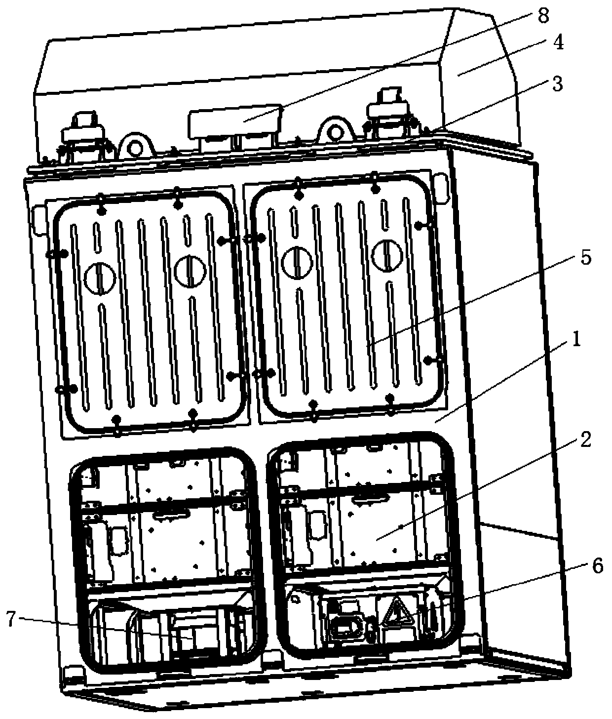
[0041] like figure 1 As shown, in this embodiment, a power battery module structure for a locomotive is specifically provided, including a casing 1 made of a steel structure to serve as a carrier for the entire module structure. Inside the casing 1 There are two power battery compartments 10 arranged side by side, and the two ends of each power battery compartment 10 are respectively provided with a battery compartment air inlet and a battery compartment air outlet, the battery compartment air inlet, the inner cavity of the power battery compartment 10 and the battery compartment The air outlet is connected to form the cooling air duct, which is used to circulate the cold air discharged through the air conditioning unit 4, and realize the heat exchange between the cold air and the heat generated by the power battery pack 2 in the cooling air duct; the power battery compartment A return air duct 13 is provided between the exterior of 10 and the housing 1 , and the return air du...

Embodiment 2

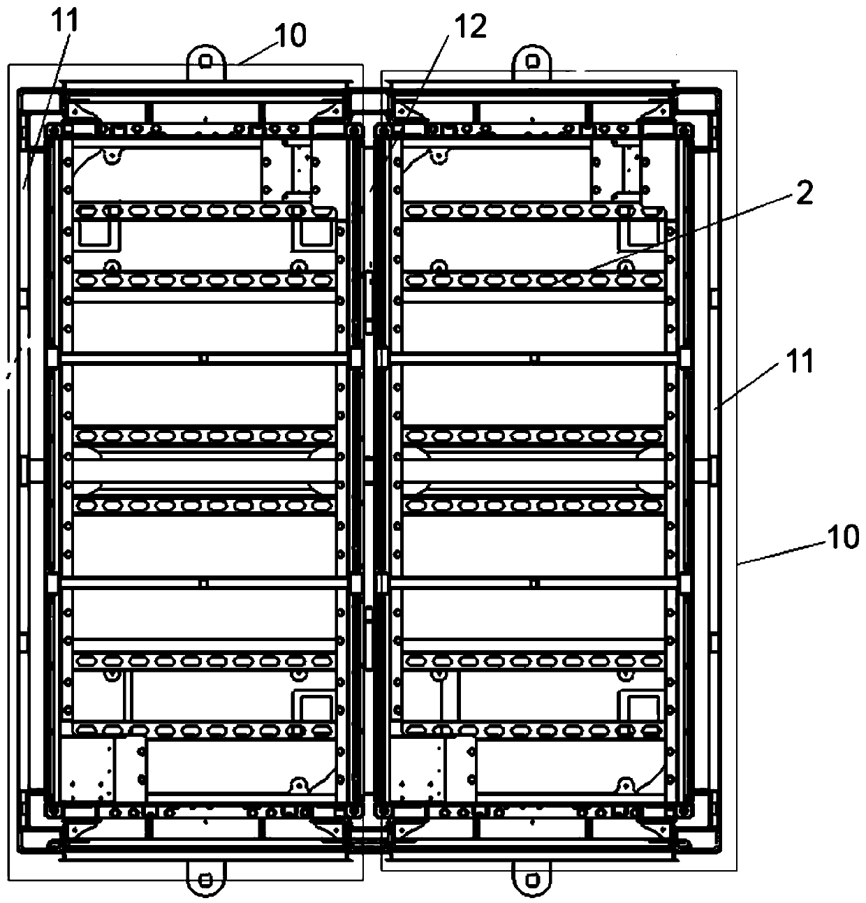
[0062] If the battery is thermally out of control, the electric energy and chemical energy inside the battery are released, and the battery will generate flammable gas, which will heat up and deflagrate. In order to further improve the fireproof and heat insulation effect of the power battery module structure, a The bottom, the side of the casing 1 and the side of the battery cavity all adopt firewalls, on the basis of Embodiment 1, such as Figure 7 As shown, the shell plate 11 on the side and bottom of the installation frame is replaced with a firewall, and the middle partition 12 that forms the power battery compartment 10 is also used as a protective wall, and the inspection door 5 and the top cover 3 The inner surfaces of the two power battery compartments 10 in Example 1 are all coated with fireproof paint, so as to finally realize the complete physical isolation of the two power battery compartments 10 in Example 1.

[0063] The firewall arranged outside the casing 1 an...

Embodiment 3

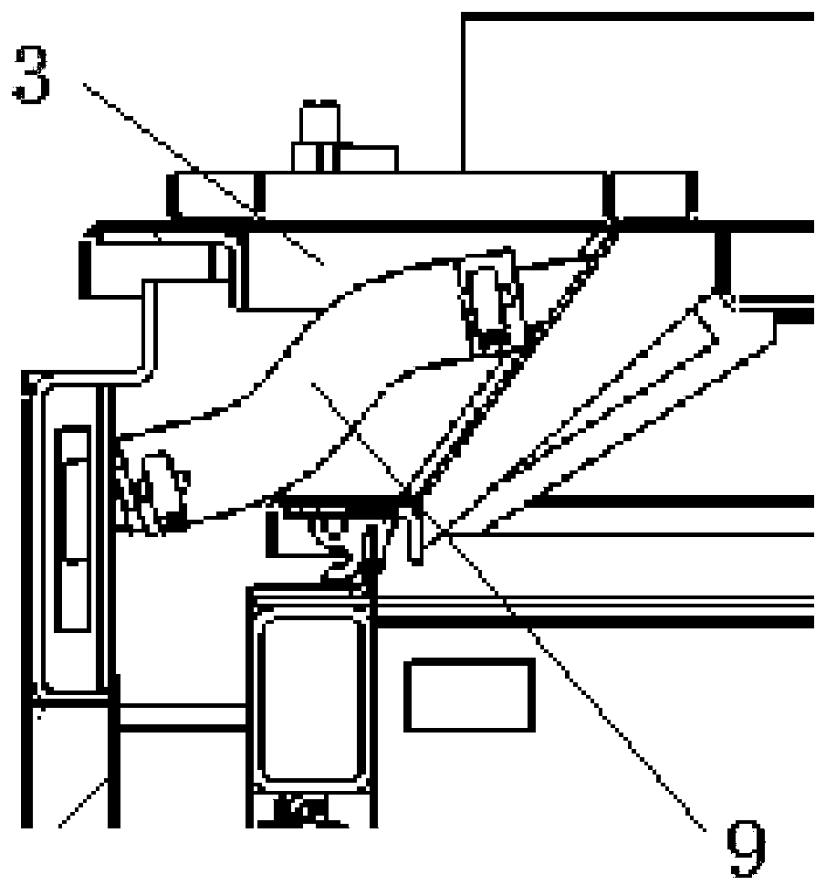
[0067] In order to further improve the fire protection system of the power battery module structure, such as Figure 9As shown, one side of the inspection door 5 is hinged on the housing 1 through a hinged shaft, and the other side is equipped with a door locking mechanism that controls the opening or closing of the inspection door 5. The door locking mechanism includes an electromagnet 20. Spring and controller. The inspection door 5 is adsorbed on the electromagnet 20 by overcoming the elastic force of the spring, and the electromagnet 20 is electrically connected to the controller. The controller is connected with a control button. When the user presses the operation button , the corresponding electromagnet 20 can be controlled to be disconnected or connected, so that the maintenance door 5 will be opened under the elastic action of the spring or be firmly adsorbed by the magnetic force of the electromagnet 20. In this embodiment, the spring can be a torsion spring And inst...


PUM


Abstract

The invention discloses a power battery module structure for a locomotive, which belongs to the technical field of power battery systems. The power battery module structure for a locomotive comprisesa shell, at least one cooling air duct is arranged in the shell, and an air return duct is arranged between the cooling air duct and the shell; at least one battery cavity is formed in the cooling airduct, a maintenance door correspondingly matched with each battery cavity is assembled on the cooling air duct in a sealing manner, and a power battery pack is arranged in each battery cavity. The structure further comprises an air conditioning unit. The air outlet of the air conditioning unit, the cooling air duct, the air return duct and the air inlet of the air conditioning unit are sequentially communicated to form a circulating passage. The structure further comprises a top cover, the top cover is assembled at the end part of the shell, and the air conditioning unit is arranged in the top cover; and a pressure relief air duct is arranged in the top cover, one end is provided with an explosion-proof pressure relief device, and the other end is communicated with the cooling air duct, so that the purposes of simplifying production and assembly requirements by realizing the internal modular design of the power battery system and improving the safety coefficient by improving the internal structure of the power battery are achieved.

Description

technical field [0001] The invention belongs to the technical field of power battery systems, and in particular relates to a power battery module structure for locomotives. Background technique [0002] Most hybrid vehicles are driven by electric motors, and the energy comes from batteries and internal combustion engines. Hybrids mostly don't need to be charged from the grid, but consume less gasoline and accelerate better. Considered a more environmentally friendly alternative to ordinary vehicles powered by internal combustion engines. [0003] The heat dissipation of the power battery system has always been a problem that has plagued the industry. The research on the heat dissipation of the power battery system has continued for many years. As the requirements of the power battery system are getting higher and higher, its energy density is also getting higher and higher, and it needs to meet the IP67 protection safety level The long service life of the power battery sys...

Claims


Application Information

Patent Timeline
Patent Type & Authority Applications(China)
IPC IPC(8): H01M2/10H01M10/613H01M10/625H01M10/6556H01M10/6565H01M10/663H01M2/12A62C3/07A62C3/16B60L50/64B60L58/26
CPCA62C3/07A62C3/16B60L50/64B60L58/26H01M2220/20H01M10/613H01M10/625H01M10/6556H01M10/6565H01M10/663H01M50/20H01M50/30Y02E60/10Y02T10/70
Inventor 叶顶康彭长福隆孝军石小佛其他发明人请求不公开姓名
Owner CRRC ZIYANG CO LTD
Why Eureka
Try Eureka