Portable two-way force application arm strength device and manufacturing method and using method thereof

A manufacturing method and a convenient technology, which can be applied to gymnastics equipment, muscle training equipment, sports accessories, etc., can solve problems such as inability to adjust the strength level of arm strength training, inability to effectively exercise back muscle groups, and injury to others when the arm strength falls off. , to achieve the effect of preventing rapid rebound, comprehensive exercise effect, and ensuring beauty and safety

Pending Publication Date: 2021-03-02
苏州昆卓精密制造有限公司
View PDF6 Cites 0 Cited by
  • Summary
  • Abstract
  • Description
  • Claims
  • Application Information

AI Technical Summary

Problems solved by technology

[0004] During the use of conventional arm strength devices, no matter whether it is a forward U-bend or a reverse U-bend, there is great danger. Incidents of arm strength devices often dropping hands and injuring oneself, and during the use of the arm strength device, it is always necessary to keep the arm facing The chest is closed, and the back muscles cannot be effectively exercised, and the strength training level of the conventional arm strength machine depends entirely on the spring material, and the training strength level cannot be adjusted for the arm strength machine with a fixed material. After a period of training, it is necessary to purchase a new one. High-level arm strength machine, the cost of exercise is higher

Method used


Image

  • Portable two-way force application arm strength device and manufacturing method and using method thereof
  • Portable two-way force application arm strength device and manufacturing method and using method thereof
  • Portable two-way force application arm strength device and manufacturing method and using method thereof

Examples


Embodiment Construction

[0035] The following will clearly and completely describe the technical solutions in the embodiments of the present invention with reference to the accompanying drawings in the embodiments of the present invention. Obviously, the described embodiments are only some, not all, embodiments of the present invention. Based on the embodiments of the present invention, all other embodiments obtained by persons of ordinary skill in the art without making creative efforts belong to the protection scope of the present invention.

[0036]In the description of the present invention, references to "an embodiment," "one embodiment," "some embodiments," or "other embodiments" mean that a particular feature, structure, or characteristic described in connection with the embodiments is included in at least some of the embodiments. in, but not necessarily all of the examples. Multiple occurrences of "an embodiment," "one embodiment," or "some embodiments" are not necessarily all referring to the...


PUM


Abstract

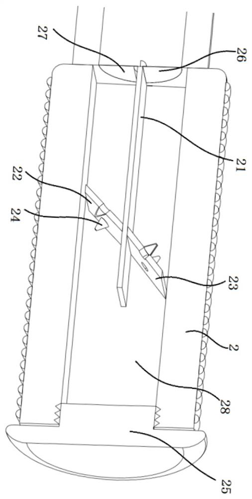
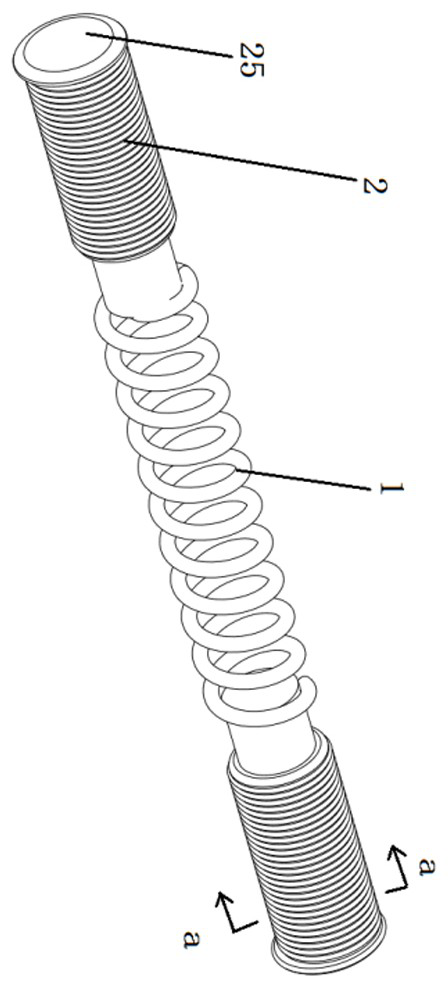
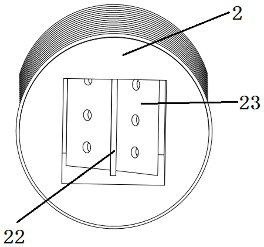
The invention discloses a portable two-way force application arm strength device and a manufacturing method and a using method thereof. The portable two-way force application arm strength device comprises a spiral spring, handles arranged near the spiral spring and buffer mechanisms located in the handle, the spiral spring is of a hollow cavity structure, and a non-Newtonian liquid is injected into a cavity of the spiral spring; and the handles are embedded into the two ends of the spiral spring respectively, openings are formed in the two ends of the spiral spring respectively, the openings are located in the handles, the two handles are fixedly connected with the two ends of the spiral spring, and the buffer mechanisms are arranged in the two handles respectively. The buffer mechanism comprises a partition plate and a buffer plate, the partition plate divides the handle into a storage cavity and a backflow cavity along the axis of the spiral spring, the buffer plate comprises a storage plate and a backflow plate, the storage plate is located on one side of the storage cavity in the handle, and the backflow plate is located on one side of the backflow cavity in the handle. Bidirectional exercise of muscles on the inner side and the outer side of the arm can be achieved, deformation can be kept, and injuries caused by springback are avoided.

Description

technical field [0001] The invention relates to a fitness equipment, in particular to a portable two-way force-applying arm strength device and a manufacturing method and a using method thereof. Background technique [0002] The arm strength machine, also known as the grip stick, is used to exercise the arm muscles, mainly to exercise the arm strength and chest muscles, to assist in the exercise of the wrist strength, to exercise the arm muscles, and the forearm wrist flexors. The positive U shape of the arm strength machine can train the triceps, pectoralis major, and middle deltoid muscle; the reverse U shape of the arm strength machine can train the biceps brachii, pectoralis major, middle deltoid muscle, and latissimus dorsi. [0003] Arm strength exercise method: 1. Bend both arms, bend the spring forcefully behind the neck; 2. Move the arms forward, bend the spring upwards, and then relax; 3. Move the arms closer to the chest, bend the spring, then straighten it, slowl...

Claims


Application Information

Patent Timeline
IPC IPC(8): A63B23/12A63B23/14A63B21/045
CPCA63B21/045A63B23/12A63B23/14
Inventor 匡红梅
Owner 苏州昆卓精密制造有限公司
Why Eureka
Try Eureka