Sedimentation device for sewage treatment

A technology of sedimentation device and sewage treatment, applied in the feeding/discharging device of sedimentation tank, sedimentation separation, sedimentation tank, etc., can solve the problem of adding sewage, etc., to achieve the effect of improving efficiency and increasing sedimentation space

Inactive Publication Date: 2021-03-02
李济平
View PDF0 Cites 2 Cited by
  • Summary
  • Abstract
  • Description
  • Claims
  • Application Information

AI Technical Summary

Problems solved by technology

[0004] Based on the technical problem that the existing sedimentation device cannot continue to add sewage to the sedimentation tank during sedimentation, the present invention proposes a sedimentation device for sewage treatment

Method used


Image

  • Sedimentation device for sewage treatment
  • Sedimentation device for sewage treatment
  • Sedimentation device for sewage treatment

Examples


Embodiment 1

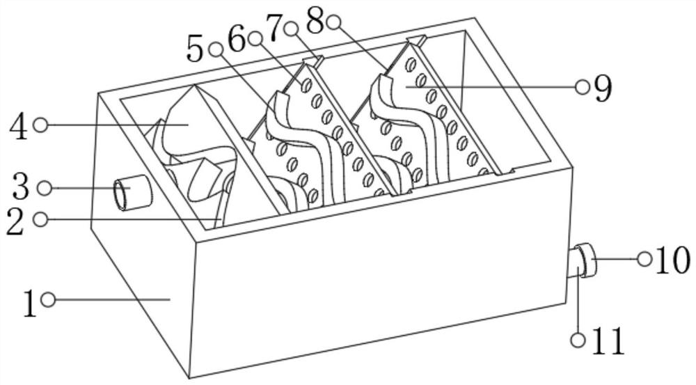
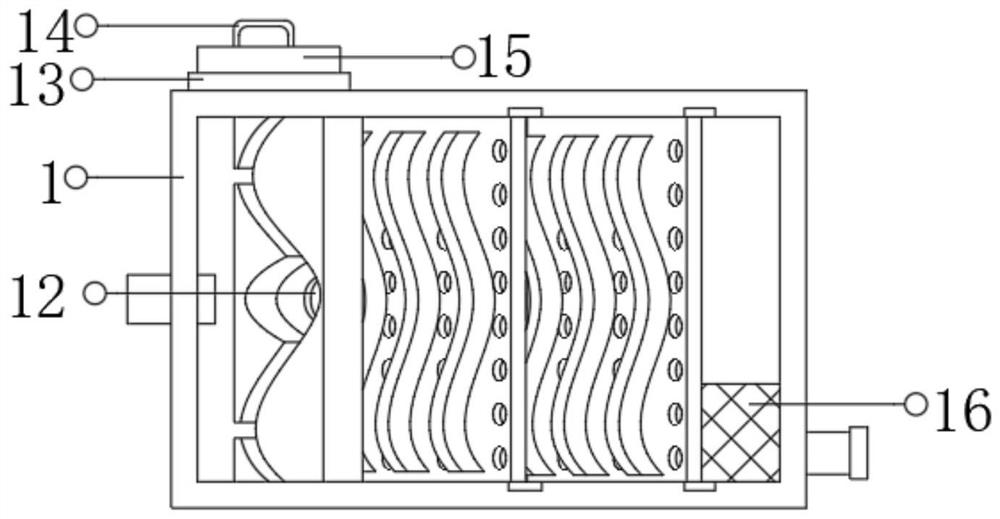
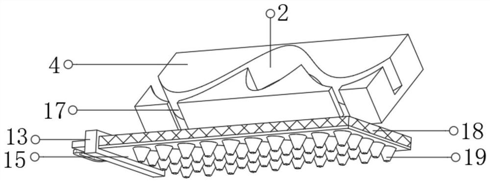
[0026] refer to Figure 1-4 , a sedimentation device for sewage treatment, comprising a sedimentation tank 1, the top of the outer wall of the sedimentation tank 1 is connected with a water inlet pipe 3 by bolts, and the water inlet pipe 3 runs through the sedimentation tank 1 and extends to the inside, and between the inner walls of the two opposite ends of the sedimentation tank 1 The slant plate 4 is connected by bolts, and the outer wall of the slant plate 4 facing the water inlet pipe 3 has a groove 2. The groove 2 is a mountain-shaped structure, and the inner wall of the bottom of the groove 2 is located in the middle. There is a deep groove 12 There are water outlets 17 at the lower ends of both sides of the groove 2 of the mountain-shaped structure, and a horizontal plate 15 is connected by bolts between the inner walls of the opposite ends of the sedimentation tank 1, and the horizontal plate 15 is located directly below the water outlet 17, and the horizontal plate 1...

Embodiment 2

[0030] refer to Figure 5 , a sedimentation device for sewage treatment, further comprising a water tank 20 connected by bolts to the outer wall on one side of the sedimentation tank 1 near the top, and a telescopic tube 22 connected to the top outer wall of the water tank 20 by bolts, and a nozzle connected to one end of the telescopic pipe 22 by bolts twenty one.

[0031]Working principle: when in use, the sewage that needs to be settled is introduced into the sedimentation tank 1 from the water inlet pipe 3, and the sewage enters from the water inlet pipe 3 and falls on the deep groove 12 in the groove 2 of the inclined plate 4, and the sewage After buffering, on the inflow groove 2, the unique mountain-shaped groove 2 can buffer the sewage again, and then flow into the filter plate 18 from the water outlet 17, and the filter plate 18 filters out the larger pollutants contained in the sewage. Impurities, when the filter plate 18 accumulates more impurities, the filter plat...


PUM


Abstract

The invention belongs to the technical field of sewage treatment, and particularly relates to a sedimentation device for sewage treatment. Aiming at the problem that an existing sedimentation device for sewage treatment cannot continuously introduce sewage in the precipitation process, the invention provides the following scheme: the sedimentation device comprises a sedimentation tank, a water inlet pipe is fixed at the top of the outer wall of one side of the sedimentation tank, an inclined plate is fixed between the inner walls of the two ends of the sedimentation tank, a groove is formed inthe outer wall of one side of the inclined plate and is of a Chinese character 'shan'(which means mountain)-shaped structure, a deep groove is formed in the inner wall of the bottom of the groove, water outlets are formed in the lower ends of the two sides of the groove of the 'shan'-shaped structure, a transverse plate is fixed between the inner walls of the two ends of the sedimentation tank, afilter plate is fixed on the outer wall of the top of the transverse plate, and a water outlet pipe is fixed in a filter hole, extending into the transverse plate, of the filter plate. According to the sedimentation device, introduced sewage can be buffered for multiple times through the groove of a 'shan'-shaped structure and the deep groove to reduce the impact force of the sewage, impurities which are completely precipitated are prevented from being excited, the sedimentation area in the tank can be increased through wave-shaped baffles and circular grooves, and sedimentation is faster andmore sufficient.

Description

technical field [0001] The invention relates to the technical field of sewage treatment, in particular to a sedimentation device for sewage treatment. Background technique [0002] The protection of water resources is achieved through water conservation on the one hand, and water recycling on the other hand. Among them, sewage treatment is a very important part of water resource recycling. Sewage treatment is widely used in construction, agriculture, transportation Energy, petrochemical, environmental protection, urban landscape, medical care, catering and other fields have increasingly entered the daily life of ordinary people. Before sewage treatment, it is often necessary to settle the sewage to make the floating objects as much as possible Precipitation reduces the difficulty of subsequent sewage treatment. [0003] However, the conventional sedimentation device for sewage treatment cannot continue to add sewage to the sedimentation tank while the sewage is settling, be...

Claims


Application Information

Patent Timeline
Patent Type & Authority Applications(China)
IPC IPC(8): B01D21/28B01D21/24B01D21/02B01D36/04
CPCB01D21/0006B01D21/0042B01D21/0045B01D21/02B01D21/2405B01D21/28B01D36/04
Inventor 李济平
Owner 李济平
Why Eureka
Try Eureka