Evaporation coating machine for high-temperature structural ceramic

A technology of steam coating machine and ceramics, which is applied in the direction of ceramic forming machines, coatings, and devices for coating liquid on the surface, etc., which can solve problems such as agglomeration, uneven coating amount of coating wheel, residual coating wheel, etc.

Inactive Publication Date: 2021-03-02
南安如盈商贸有限公司
View PDF0 Cites 1 Cited by
  • Summary
  • Abstract
  • Description
  • Claims
  • Application Information

AI Technical Summary

Problems solved by technology

[0004] Because the steam coating machine needs to spread the high-temperature ceramic powder material on the coating wheel below at a uniform speed during the coating operation, and make it rotate to carry out contact pressure steam coating of the material to be coated. Since the ceramic powder is in the trough, there will be condensation Block phenomenon, when falling down, block ceramic material will appear on the coating wheel, resulting in uneven coating amount on the coating wheel, and after touching the pressure, there will be some residue on the coating wheel, which will affect the steam coating Effect

Method used


Image

  • Evaporation coating machine for high-temperature structural ceramic
  • Evaporation coating machine for high-temperature structural ceramic
  • Evaporation coating machine for high-temperature structural ceramic

Examples


Embodiment 1

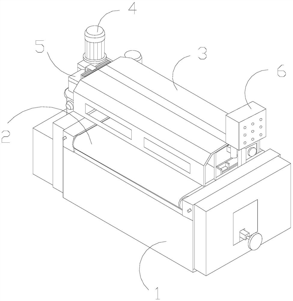
[0027] as attached figure 1 to attach Figure 5 Shown:

[0028] The invention provides a steam coating machine for high-temperature structural ceramics, the structure of which is provided with a frame 1, a running table 2, a working frame 3, a motor 4, a side connecting shaft 5, and a control panel 6, and the running table 2 is movable on the frame 1, the work frame 3 is connected above the frame 1, the work frame 3 is located above the running platform 2 and is movably matched, the motor 4 is installed on one side of the frame 1, and the side connecting shaft 5 Passing through one side of the working frame 3 , the control panel 6 is installed on the other side of the working frame 3 .

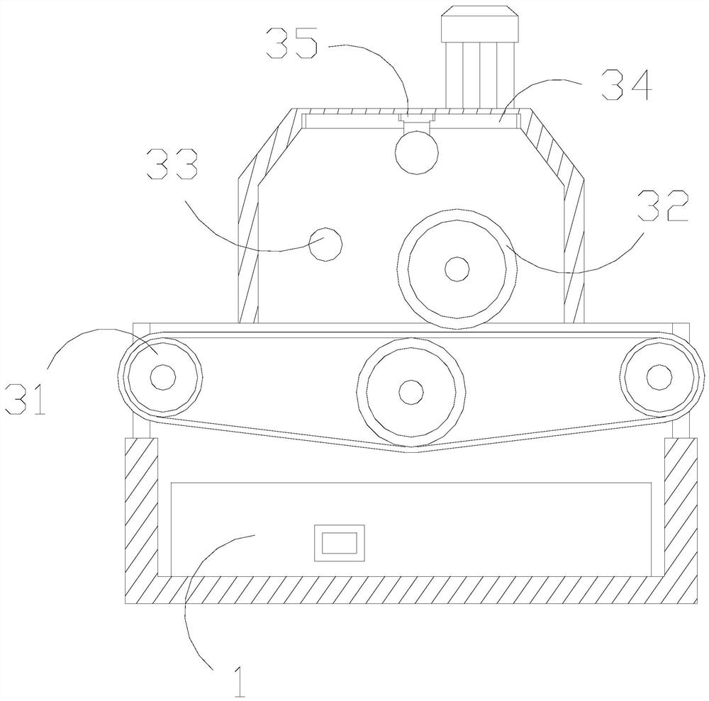
[0029] The working frame 3 is provided with a spreading roller 31, a coating wheel 32, a bearing 33, a top rail 34, and a drop rack 35. The spreading roller 31 is movable on both sides below the working frame 3, and the coating wheel 32 is movably connected to the working frame. Inside the ...

Embodiment 2

[0035] as attached Figure 6 to attach Figure 7 Shown:

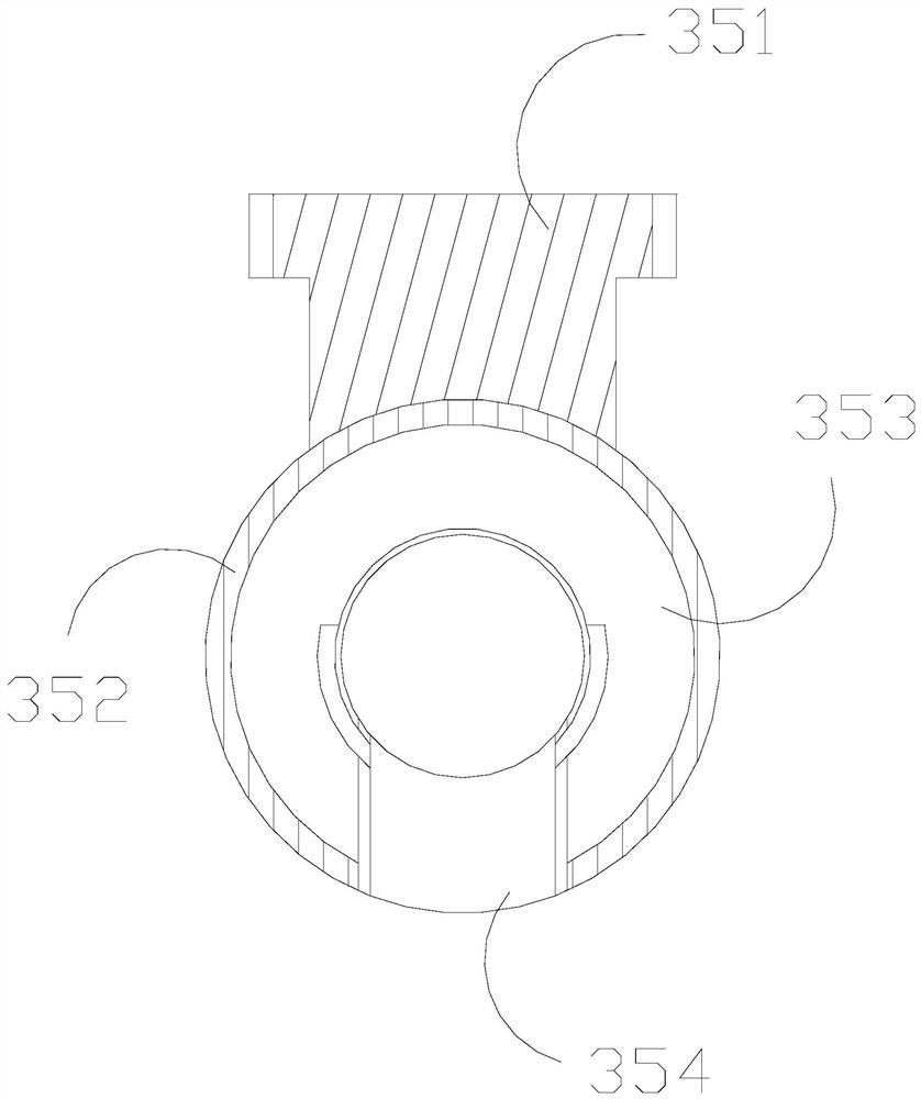
[0036]Wherein, the movable cavity 353 is provided with a hinged swing rod z1, a slamming ball z2, a spring steel z3, and a hinged bearing z4. The bearing z4 is hingedly connected and movably matched. The side support block a3 is connected to the inner end of the hinge swing rod z1 and is movably fitted. There are six hinge swing rod z1 and slamming ball z2, and each two are used as a group for activities. Coordinated, there are three spring steel z3, the lashing ball z2 is in a spherical state, and the hinge swing rod z1 is continuously hinged and oscillated under the elastic action of the spring steel z3, driving the lashing ball z2 to continuously perform impacting activities.

[0037] Wherein, the slamming ball z2 is provided with a solid ring z21, a ring cavity z22, a linkage bag z23, and a pull belt z24. The ring cavity z22 is located outside the center ring z21, and the linkage bag z23 is embedded in the ring ca...


PUM


Abstract

The invention discloses an evaporation coating machine for high-temperature structural ceramic. The evaporation coating machine is structurally provided with a rack, an operation table, a working frame, a motor, a side connecting shaft and a control panel, a solid clamping block rotates to drive a trough to integrally rotate, powder on the inner side of the trough can be turned back and forth to be activated, conical striking heads are matched with bottom springs, the front ends of the conical striking heads are of a conical structure, so as to facilitate penetrating through powder, meanwhile,the the conical striking heads continuously retract and eject to scatter caked powder in the powder continuously, impact balls are driven to continuously impact the outer wall of the trough, under the auxiliary effect of spring steels, the swing range of hinge swing rods is larger, and the hinge swing rods can conveniently drive the impact balls to conduct faster knocking movement to vibrate thetrough, so that the powder is continuously scattered through vibration, and linkage bags bear extrusion force to be subjected to concave shrinkage deformation when being struck, so that the whole impact balls are subjected to deformation in a fluctuating state, and the powder can be more quickly and actively bounced off in the knocking process and after the powder is attached to the impact balls.

Description

technical field [0001] The invention belongs to the field of high-temperature structural ceramic equipment, and more specifically relates to a steam coating machine for high-temperature structural ceramics. Background technique [0002] High-temperature structural ceramics have high melting point, high-temperature creep resistance, oxidation and corrosion resistance, etc., and are high-temperature structural materials that can be used in equipment or devices to withstand mechanical loads under high-temperature conditions. It is widely used in the field of coating on steam coating machines. [0003] Based on the above-mentioned inventor's discovery, the steam coating machine of existing high-temperature structural ceramics has the following deficiencies: [0004] Because the steam coating machine needs to spread the high-temperature ceramic powder material on the coating wheel below at a uniform speed during the coating operation, and make it rotate to carry out contact pres...

Claims


Application Information

Patent Timeline
IPC IPC(8): B05C19/04B05C19/06B28B19/00
CPCB05C19/04B05C19/06B28B19/00
Inventor 杨伟锋
Owner 南安如盈商贸有限公司
Why Eureka
Try Eureka