Welding device

A technology of welding device and generating device, which is applied in the direction of auxiliary devices, welding equipment, auxiliary welding equipment, etc., which can solve the problems of affecting welding efficiency and welding quality, easy oxidation of weld seam, poor fixation of welding joints of pipe fittings, etc.

Pending Publication Date: 2021-03-02
陈虎
View PDF1 Cites 2 Cited by
  • Summary
  • Abstract
  • Description
  • Claims
  • Application Information

AI Technical Summary

Problems solved by technology

[0006] Aiming at the deficiencies of the prior art, the present invention provides a welding device, which solves the problem of the poor fixation of the welding joint of the pipe fittings when the traditional welding equipment is turned over, which easily causes the fracture of the welding joint and affects the welding efficiency and welding quality. The traditional welding environment For aerobic welding, the weld is easily oxidized in a high-temperature aerobic environment, which affects the stability of the weld

Method used


Image

  • Welding device
  • Welding device
  • Welding device

Examples


Embodiment 1

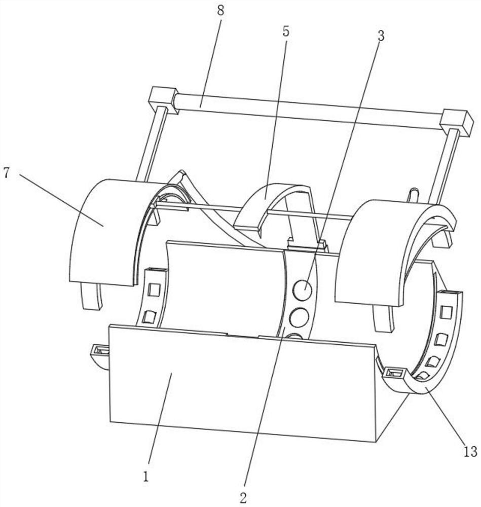
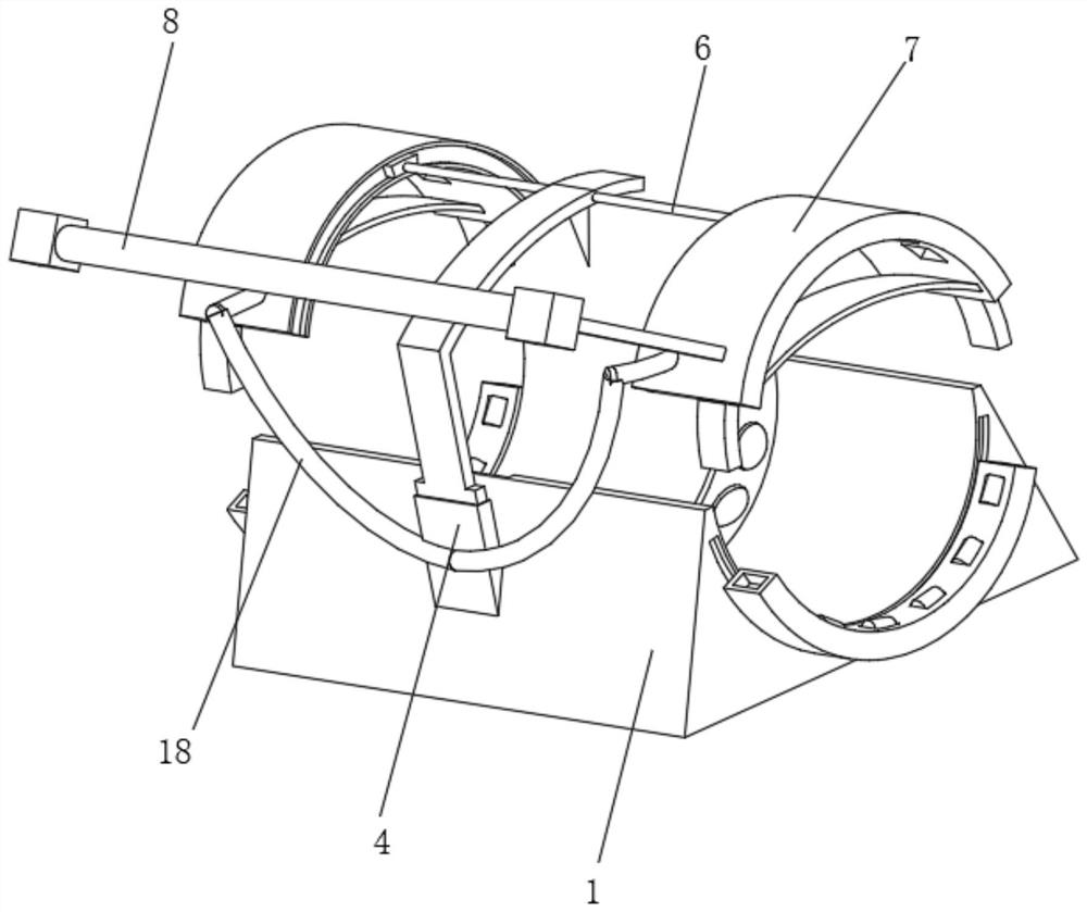
[0043] Such as Figure 1-5 As shown, the present invention provides a technical solution: a welding device, including a welding base 1, the middle position inside the welding base 1 is fixedly connected with a welding regulating groove 2, and the surface of the welding regulating groove 2 is uniformly provided with regulating nozzle holes 3, The middle position on the back of the welding base 1 is fixedly connected with an air pressure generating device 4, and the top of the air pressure generating device 4 is fixedly connected with a welder 5, and the left and right sides of the welder 5 near the top are rotatably connected with a support link 6, and the support link 6 Both sides of the limit plate 7 are provided with a limit plate 7, the side of the limit plate 7 close to the back is fixedly connected with a hand-held control lever 8, and the end of the limit plate 7 near the inner side is fixedly connected with a moving track 9, and the inner sliding connection of the move t...

Embodiment 2

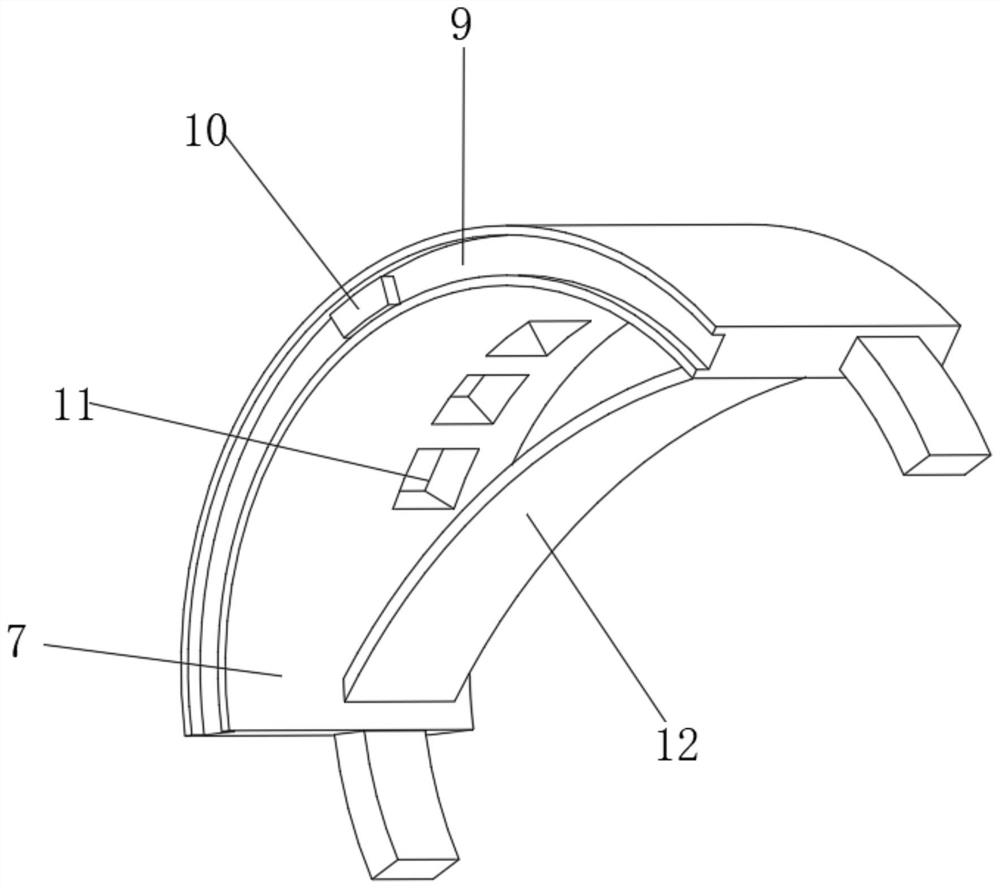
[0048] Such as Figure 6-7 As shown, on the basis of Embodiment 1, the present invention provides a technical solution: the state adjustment mechanism 11 includes a limiting inner groove 111, which is uniformly arranged on the inner surface of the limiting pressure plate 7, and the middle of the inner limiting groove 111 An adjustment drive block 112 is connected to the position rotation, and the adjustment drive block 112 is arranged corresponding to the pressing elastic piece 12 .

[0049] A sealing driving groove 113 is fixedly connected to the inside of the pressing elastic sheet 12 and located on the side of the limiting inner groove 111 , and a driving push plate 114 is slidably connected to the inside of the sealing driving groove 113 .

[0050] One side inside the sealed driving groove 113 evenly runs through and is rotatably connected with a conductive wheel 115 , and one end of the conductive wheel 115 extends to limit the inner groove 111 and is fixedly connected wi...

Embodiment 3

[0054] Such as Figure 8 As shown, on the basis of Embodiment 1 and Embodiment 2, the present invention provides a technical solution: a welding device, the air pressure generating device 4 includes a collection inner tube 41, and the bottom of the collection inner tube 41 is fixedly connected to the welding base 1 , the left side outside the collection inner pipe 41 is fixedly communicated with a nitrogen tank 42 . The purpose of ensuring sufficient nitrogen supply and quantitative discharge of nitrogen at the same time is to avoid nitrogen waste.

[0055] The top of the collection inner tube 41 is fixedly connected with a sealed booster tube 43 , the inside of the sealed booster tube 43 is penetrated and slidably connected with a booster drive rod 44 , and the top of the booster drive rod 44 is fixedly connected with the welder 5 . The air around the pipe is blown away, and nitrogen is filled on the surface of the pipe to achieve the purpose of oxygen barrier welding.

[0...


PUM


Abstract

The invention discloses a welding device. The welding device comprises a welding base; a welding regulation and control groove is fixedly connected to the middle of the interior of the welding base; regulation spray holes are evenly formed in the surface of the welding regulation and control groove; an air pressure generation device is fixedly connected to the middle of the back face of the welding base; a welding apparatus is fixedly connected to the top of the air pressure generation device; supporting connecting rods are rotationally connected to the left side and the right side, close to the upper portion, of the welding apparatus; limiting pressing plates are arranged on the two sides of each supporting connecting rod; hand-held control rods are fixedly connected to the sides, close to the back face, of the limiting pressing plates; state adjusting mechanisms are fixedly connected to the middles in the limiting pressing plates; and a touch elastic sheet is fixedly connected to themiddle position of the bottom of the corresponding limiting pressing plate and located below the corresponding state adjusting mechanism. The welding device relates to the technical field of welding.According to the welding device, mechanical driving is achieved by changing the pressure intensity, workers can conveniently change the air pressure state at any time, switching between the pressurization state and the normal pressure state is achieved, and the driving stability is high.

Description

technical field [0001] The invention relates to the technical field of welding, in particular to a welding device. Background technique [0002] Welding, also known as welding, is a manufacturing process and technique that uses heat, high temperature, or pressure to join metal or other thermoplastic materials such as plastics. [0003] For example, the Chinese invention publication number is: CN105171292A, a pipe fitting welding device, comprising: a housing, a ring gear, a gear mechanism, a driving mechanism and a control mechanism; There is an opening on the radial side; a notch corresponding to the opening is provided on the radial side of the ring gear. The pipe fitting welding device is also equipped with a return detection mechanism to detect whether the opening and the notch overlap. The return detection mechanism and the control mechanism are electrically connected. connected, and send a signal to the control mechanism when the opening does not coincide with the not...

Claims


Application Information

Patent Timeline
IPC IPC(8): B23K37/00B23K37/047B23K37/053
CPCB23K37/00B23K37/0443B23K37/047B23K37/0533
Inventor 陈虎
Owner 陈虎
Why Eureka
Try Eureka