Cutting device for building

A cutting device and construction technology, applied in the direction of stone processing tools, work accessories, manufacturing tools, etc., can solve the problems of separation from cutting equipment, low tile cutting efficiency, unfavorable batch cutting, etc.

Inactive Publication Date: 2021-03-02
李良容
View PDF1 Cites 0 Cited by
  • Summary
  • Abstract
  • Description
  • Claims
  • Application Information

AI Technical Summary

Problems solved by technology

[0006] Aiming at the deficiencies of the prior art, the present invention provides a cutting device for construction, which solves the need to fix the tiles in the current tile cutting process, so that the tile cutting efficiency i

Method used


Image

  • Cutting device for building
  • Cutting device for building
  • Cutting device for building

Examples


Embodiment 1

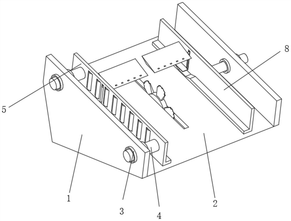
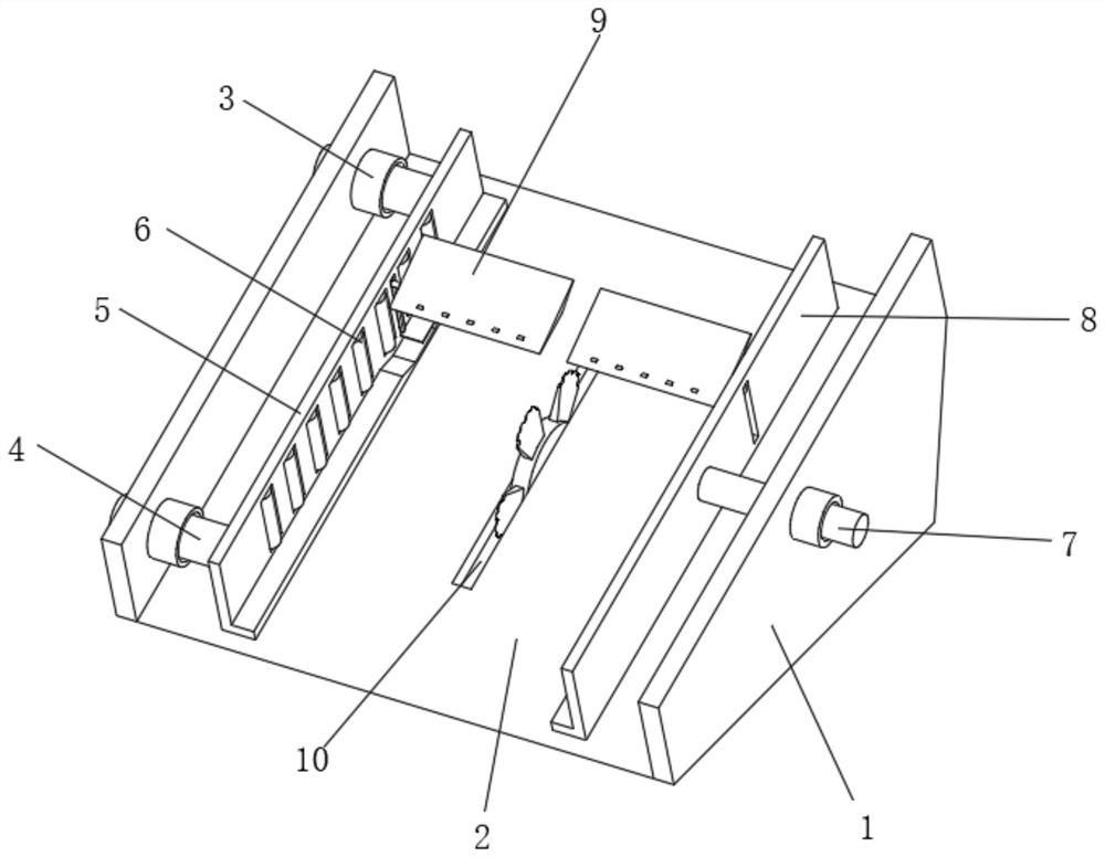
[0041] like Figure 1-3 As shown, the present invention provides a technical solution: a cutting device for construction, including an outer support frame 1, the middle position of the outer support frame 1 is fixedly connected with a guide inclined plate 2, and the front position of the guide inclined plate 2 is connected with the outer support frame. 1. The bottom of the front is on the same level. The front and rear ends on the left side of the outer support frame 1 are fixedly connected to the elastic sleeve rod 3 above the guide slant plate 2. The elastic sleeve rod 3 runs through and is slidably connected to the adjustment insert rod 4 One end of the adjustable plunger 4 located at the inner side of the outer support frame 1 is fixedly connected with a movable splint 5, the bottom of the movable splint 5 is arranged parallel to the top surface of the guide inclined plate 2, and the inside of the movable splint 5 is evenly and equidistantly rotated and connected with limit...

Embodiment 2

[0043] like Figure 4-6 As shown, on the basis of Embodiment 1, the present invention provides a technical solution: a cutting device for construction, the limiting pressing mechanism 9 includes a turning table groove 91, and the turning table groove 91 is arranged on the surface of the bottom of the movable splint 5, The position close to the back of the steering table groove 91 is rotatably connected with a pressure variable carrier plate 92 , and the pressure variable carrier plate 92 is arranged above the steering table groove 91 . Relieve the impact force during the initial cutting, realize the protection of the tile end when it is just cut, and avoid knocking damage when the end is just cut.

[0044] The turntable groove 91 adopts a large-up and down-small prism groove structure, and the turntable groove 91 and one end of the cutting drive mechanism 11 back are on the same level.

[0045] The inside of the movable splint 5 and the position between the limiting pulleys 6...

Embodiment 3

[0050] like Figure 7-9 As shown, on the basis of Embodiment 1 and Embodiment 2, the present invention provides a technical solution: a cutting device for construction, the end of the pressing cone plate 95 away from the adjustment slider 94 is fixedly connected with a magnet block 97, and the magnet The block 97 is arranged corresponding to the cutting drive mechanism 11 . The magnetic repulsion ensures the stability of the bricklaying in the vertical direction during the whole cutting process.

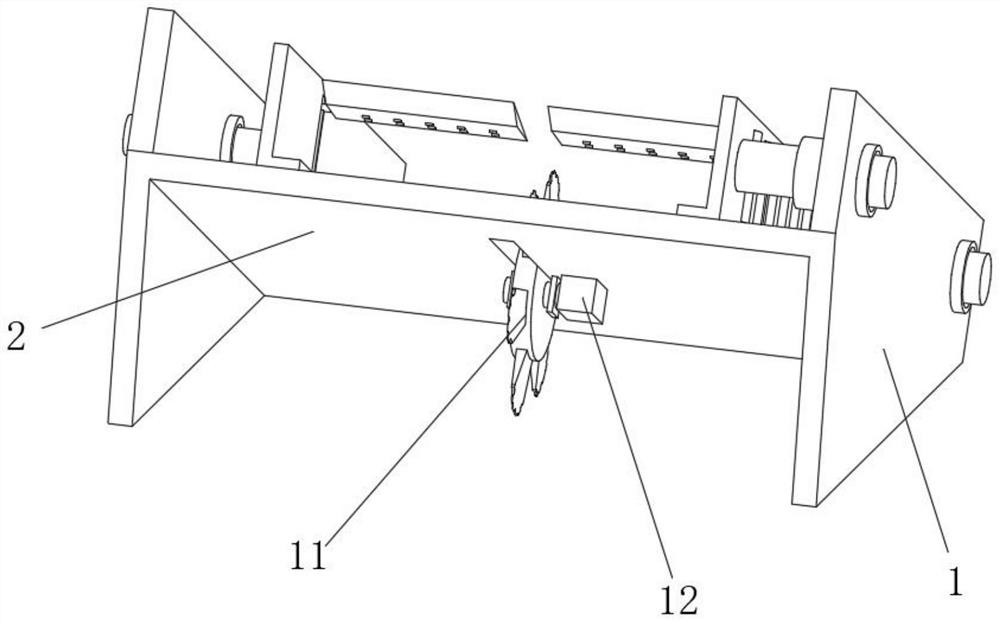
[0051] Cutting drive mechanism 11 comprises driving disk 111, and the circle center position outside driving disk 111 is fixedly connected with drive motor 12 output shafts, and the outer surface of driving disk 111 is evenly fixedly connected with cutting blade 112, and the outer surface of driving disk 111 and A contact cleaning assembly 113 is fixedly connected between the cutting blades 112 .

[0052] Both sides of the cutting blade 112 outside are fixedly connected with a push...


PUM


Abstract

The invention discloses a cutting device for a building. The cutting device comprises an outer supporting frame, a guide inclined plate is fixedly connected to the middle of the outer supporting frame, elastic sleeve rods are fixedly connected to the front end and the rear end of the left side of the outer supporting frame and located above the guide inclined plate, adjusting inserting rods are connected into the elastic sleeve rods in a penetrating and sliding mode, movable clamping plates are fixedly connected to the ends, located on the inner side of the outer supporting frame, of the adjusting inserting rods, limiting pulleys are evenly and rotationally connected into the movable clamping plates at equal intervals, adjusting clamping plates are rotationally connected to the ends, located on the inner side of the outer supporting frame, of adjusting threaded rods, limiting pressing mechanisms are symmetrically and fixedly connected to the positions close to the back faces of the movable clamping plates, and a cutting driving mechanism is rotatably connected to the interior of a cutting through groove. The invention relates to the technical field of buildings. According to the cutting device for the building, active feeding is achieved through the gravity of ceramic tiles, meanwhile, the cutting centrifugal force direction is perpendicular to the ceramic tile feeding moving direction, the ceramic tiles are prevented from shaking under the influence of multi-angle force, and cutting stability is guaranteed.

Description

technical field [0001] The invention relates to the technical field of construction, in particular to a construction cutting device. Background technique [0002] Construction refers to the assets made by man-made construction, which belongs to the category of fixed assets, including two categories: houses and structures. Housing refers to engineering buildings for people to live, work, study, produce, operate, entertain, store items and carry out other social activities. [0003] As the Chinese invention publication number is: CN101941242A a kind of adobe cutting machine. The present invention adopts the following technical scheme, the frame is provided with rails, the lower parts of the two sides of the trolley are provided with wheels, which form a rolling fit with the rails, the dragging plate of the trolley and the surface of the compacted plate are located in the horizontal plane, and movable knives are installed on the trolley There is a cutting tool on the movable ...

Claims


Application Information

Patent Timeline
IPC IPC(8): B28D1/24B28D7/00B28D7/02B28D7/04
CPCB28D1/24B28D7/00B28D7/02B28D7/04
Inventor 李良容
Owner 李良容
Why Eureka
Try Eureka